 Yongce Group Co., Ltd.
YCJP Series Outdoor Integrated Distribution Box - Complete Product Introduction
1. Product Brief Introduction
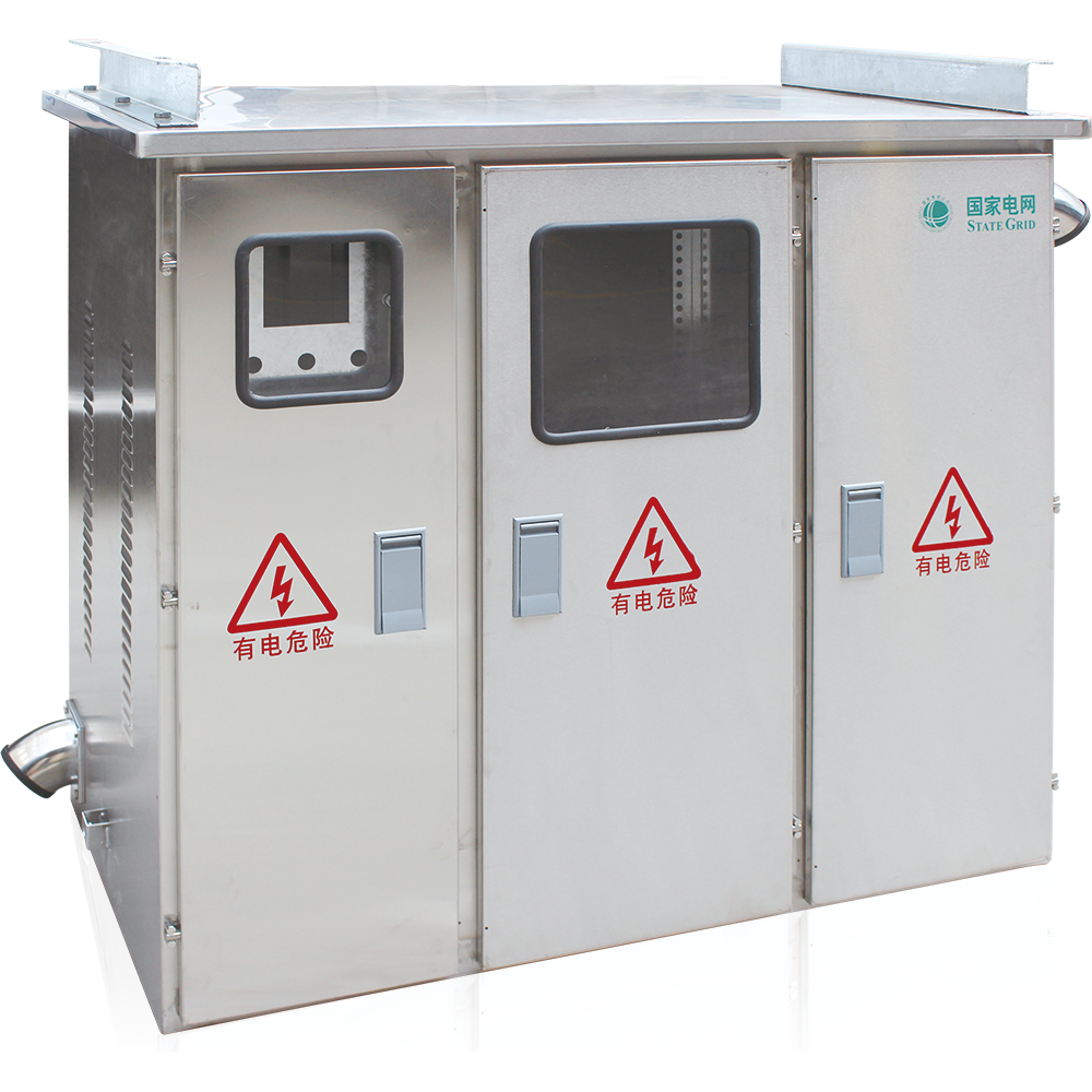
The YCJP series outdoor integrated distribution box integrates multiple functions such as metering, outgoing line, and reactive power compensation into one outdoor comprehensive distribution device. It has protection functions including short circuit, overload, overvoltage, and leakage protection. With small size, beautiful appearance, economy and practicality, it is installed on the electric pole of the outdoor pole-mounted transformer, and is an ideal supporting product for urban and rural power grid transformation.
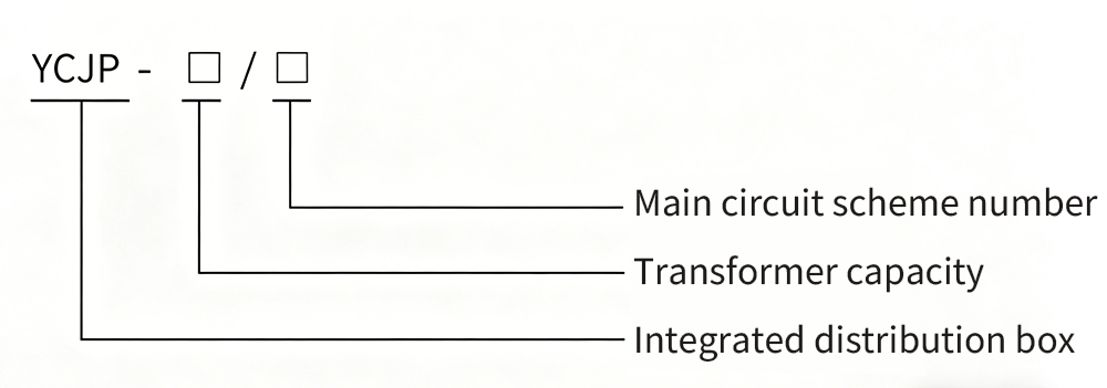
2. Model Meaning & Explanation
The coding of the product model contains the core parameter information of the distribution box. The specific meaning of each part of the model is as follows:
3. Normal Operating Environmental Conditions
- Ambient temperature: -25℃ ~ +40℃;
- Air relative humidity: daily average value not more than 90%, monthly average value not more than 90%;
- Altitude: not more than 2000m;
- Installed in places without severe vibration, impact and corrosive gas.
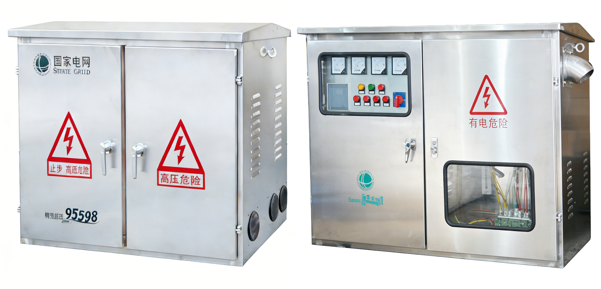
4. Structural Characteristics
- The cabinet body is available in vertical and horizontal structures. The outer shell is made of 2mm high-quality stainless steel plate processed by multi-fold edge technology, or stainless steel sandwich composite board with honeycomb structure, which has flame retardant, environmental protection, heat insulation, anti-condensation and other properties.
- Adopting special stainless steel welding process, the cabinet body has high strength after forming, smooth and clean surface without welding marks; the internal installation plate is treated with galvanization to ensure no rust for 20 years.
- The front and rear doors of the cabinet are convenient for user operation and maintenance. The doors are equipped with high-elasticity and aging-resistant sealing strips, and each door is equipped with two kinds of door locks with clear anti-theft and anti-misoperation marks.
- The metering room is fully closed with lead sealing device; the side of the cabinet body is equipped with wire inlet and outlet pipes to prevent rain and foreign matters; the bottom is provided with ventilation holes and power outlet holes, and the top is equipped with ventilation channels and wire mesh, which has the functions of waterproof, rust proof, dust proof and anti-theft.
- Protection grade: IP54.
5. Main Technical Parameters
| Serial No. | Name | Unit | Parameter |
|---|---|---|---|
| 1 | Transformer Capacity | kVA | 30-400 |
| 2 | Rated Working Voltage | V | 400 |
| 3 | Auxiliary Working Voltage | V | AC220, AC380 |
| 4 | Rated Frequency | Hz | 50 |
| 5 | Rated Current | A | ≤630 |
| 6 | Rated Leakage Action Current | mA | 30-300 (Adjustable) |
| 7 | Protection Grade | - | IP54 |
6. Main Components Description
-
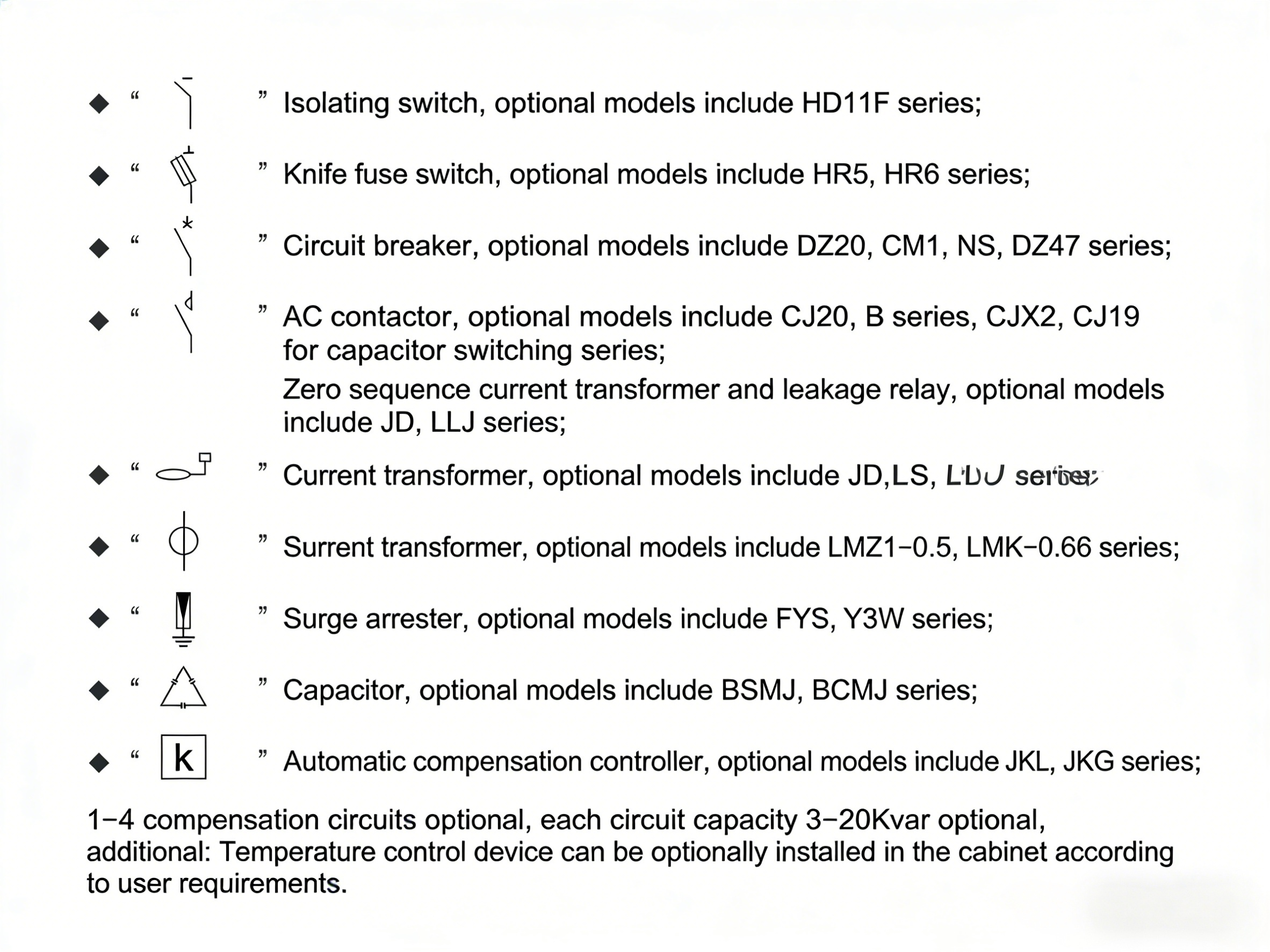 Isolating switch, model can be selected from HD11F series;
- Knife switch, model can be selected from HR5, HR6 series;
- Circuit breaker, model can be selected from DZ20, CM1, NS, DZ47 series;
- AC contactor, model can be selected from CJ20, B series, CJX2, CJ19 (reactive power compensation capacitor) series;
- Zero sequence current transformer and leakage protector, model can be selected from JD, LLJ series;
- Current transformer, model can be selected from LZJ-0.5, LMK-0.66 series;
- Surge arrester, model can be selected from YS, Y3W series;
- △: Capacitor, model can be selected from SMJ, BCMJ series;
- K: Automatic reactive power compensation controller, model can be selected from JK, JKG series; the number of compensation loops can be selected from 1-4, and the capacity per loop is 3-20kvar optional;
-
In addition: Temperature control device can be optionally equipped according to user requirements.
7. Cabinet Overall Dimensions
7. Cabinet Overall Dimensions
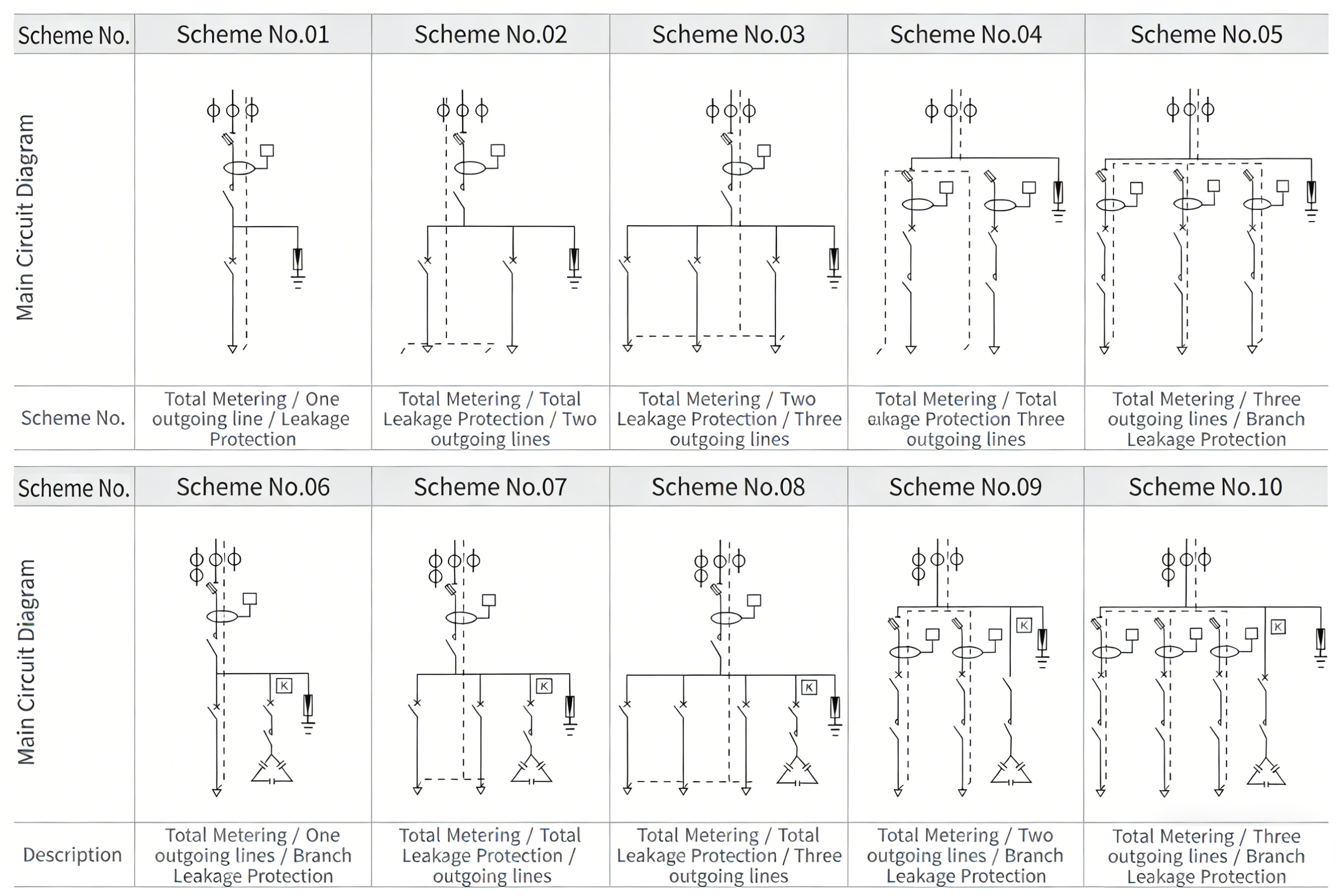
7.1 Horizontal Cabinet Dimensions
| Transformer Capacity (kVA) | Scheme No. | L (mm) | W (mm) | H (mm) |
|---|---|---|---|---|
| 30-100 | 01, 06 | 800 | 450 | 700 |
| 30-250 | 02, 04, 07, 09 | 900 | 500 | 700 |
| 100-400 | 03, 05, 08, 10 | 1100 | 600 | 800 |
7.2 Vertical Cabinet Dimensions
| Transformer Capacity (kVA) | Scheme No. | L (mm) | W (mm) | H (mm) |
|---|---|---|---|---|
| 30-100 | 01, 05 | 600 | 450 | 1000 |
| 30-250 | 02, 04, 07, 09 | 700 | 500 | 1000 |
| 100-400 | 03, 05, 08, 10 | 800 | 600 | 1100 |
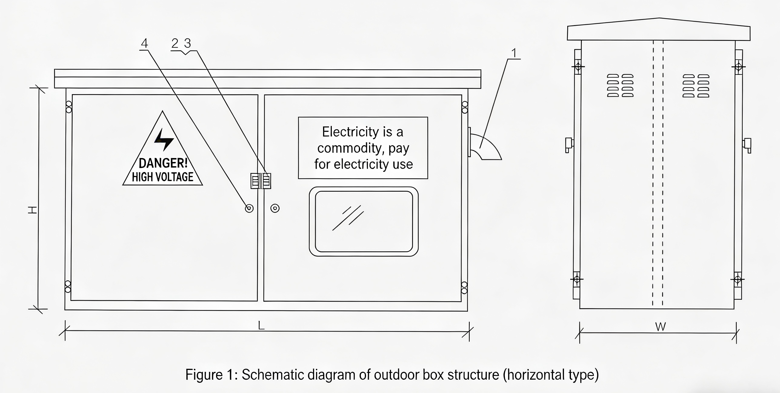
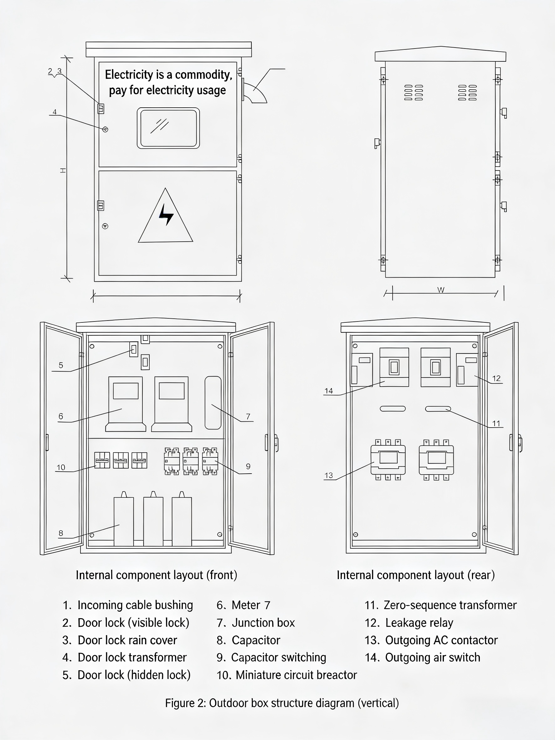
7.3 Schematic Diagram of Box Structure

-12/0.4(F·R) Outdoor Prefabricated Substation (European Style)")
-12 Outdoor High-Voltage Vacuum Circuit Breaker / Primary and Secondary Integration (with Directional Judgment)")


