 Yongce Group Co., Ltd.
Intelligent Integrated Substation Product Introduction
1. Product Brief Introduction
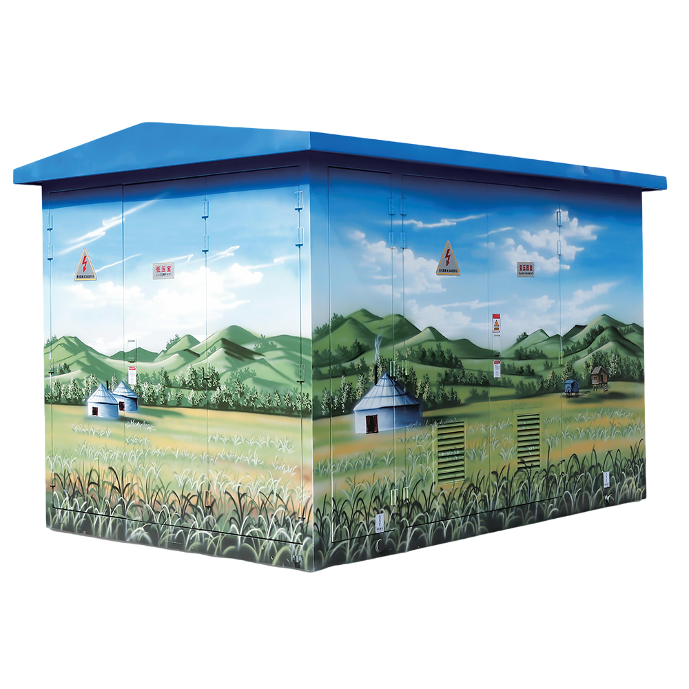
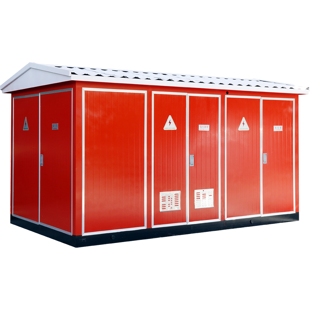
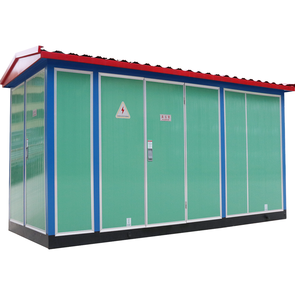
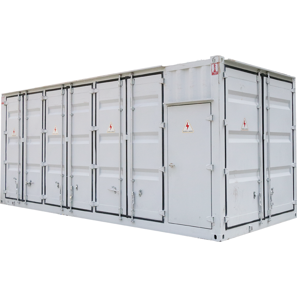
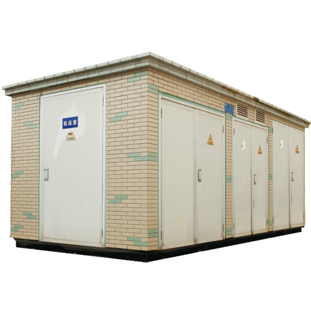
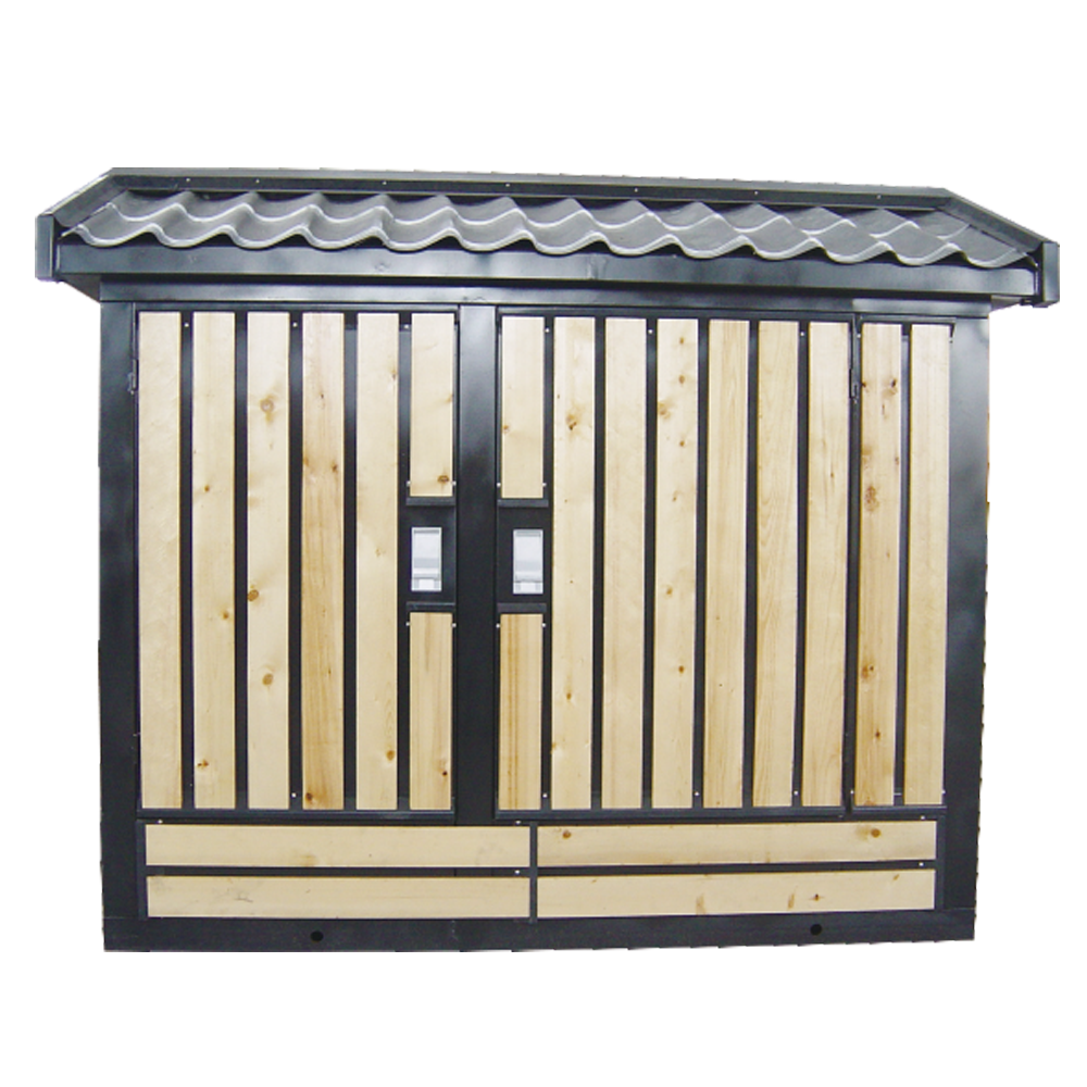
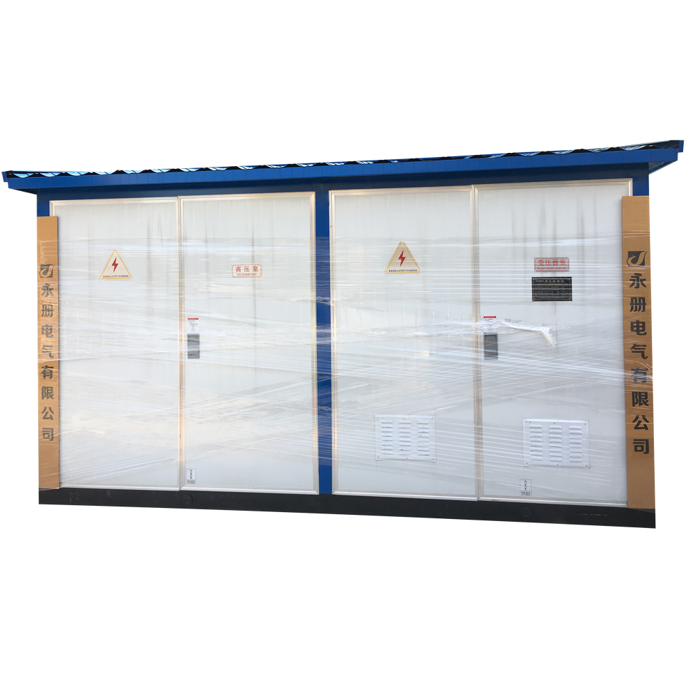
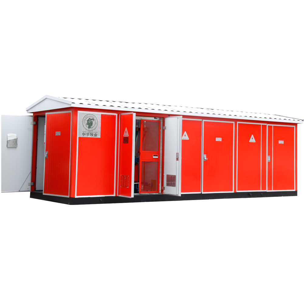
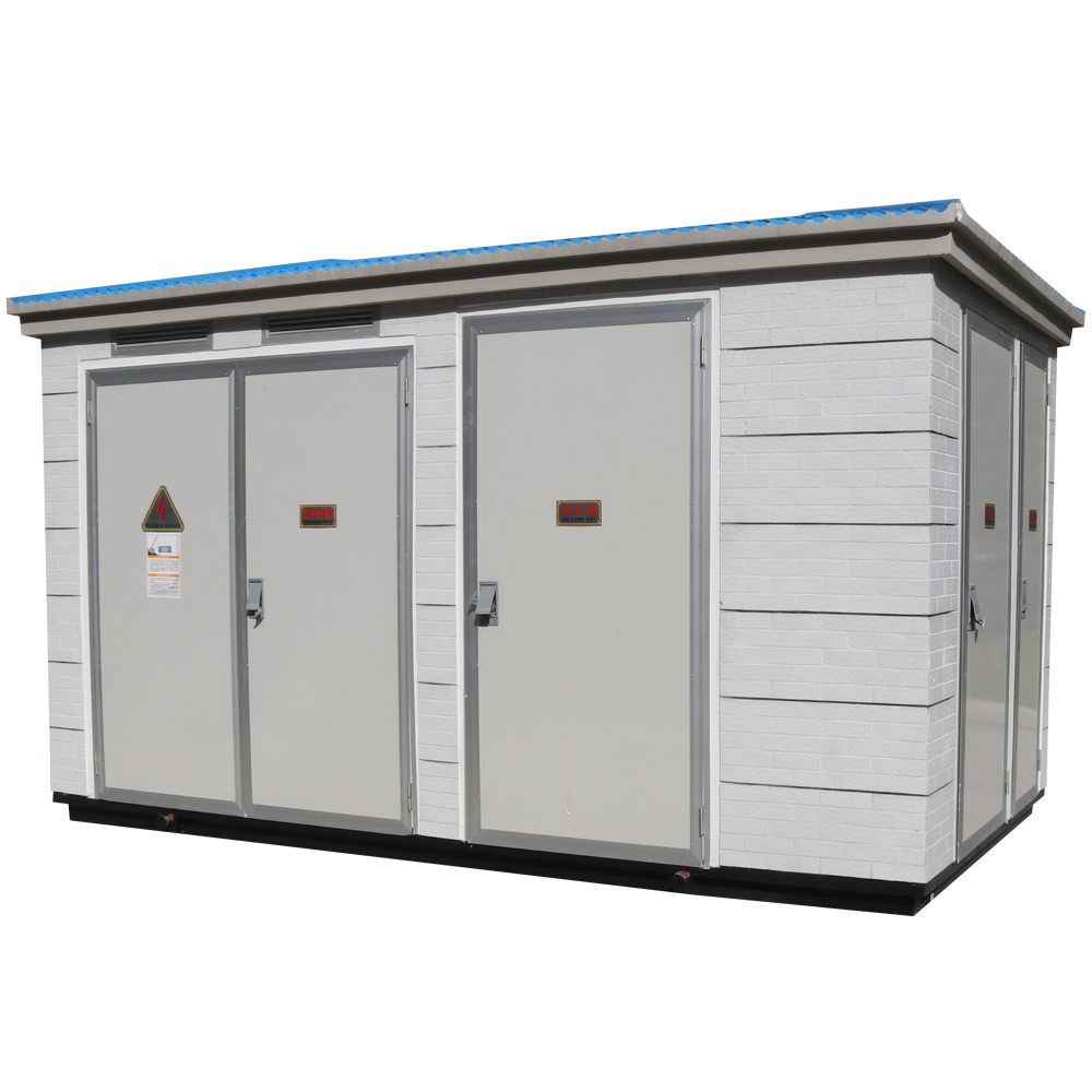
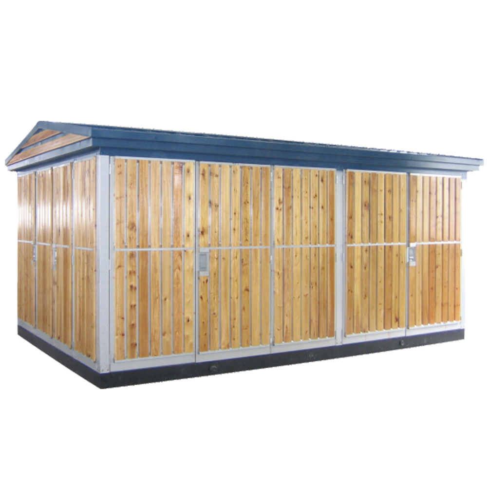
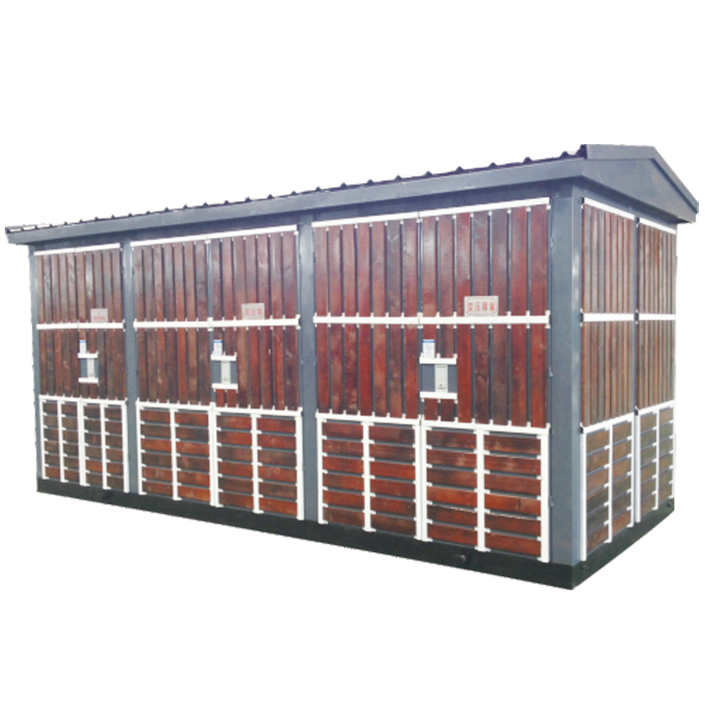
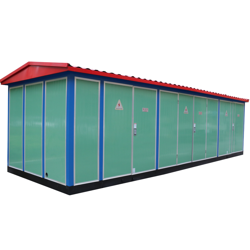
The intelligent integrated substation (YB series) is widely used in urban power grid renovation, residential districts, high-rise buildings, industrial and mining areas, hotels, shopping malls, airports, railways, oil fields, docks, highways and temporary power supply places, both indoor and outdoor.
2. Model Meaning & Explanation
The coding of the product model contains the core structural characteristics and parameter information of the substation. The specific meaning of each part of the model is as follows:
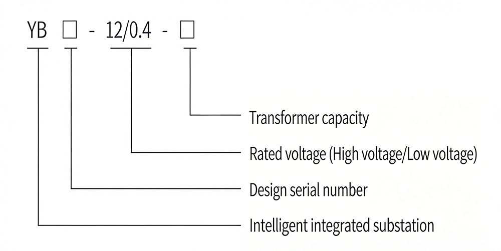
YB: Transformer Capacity (kVA, filled in the last square)
□: Rated Voltage (High Voltage / Low Voltage) (kV)
12/0.4: Design Serial Number
□: Intelligent Integrated Substation (Main Code)
3. Operating Conditions
- Installation altitude shall not exceed 1000m;
- Ambient temperature: -25℃ ~ 40℃;
- Relative humidity: daily average value not more than 95%, monthly average value not more than 90%;
- Installation site: no fire, explosion, chemical corrosive gas and severe vibration. If exceeding the above conditions, users can negotiate with our company.
4. Product Characteristics
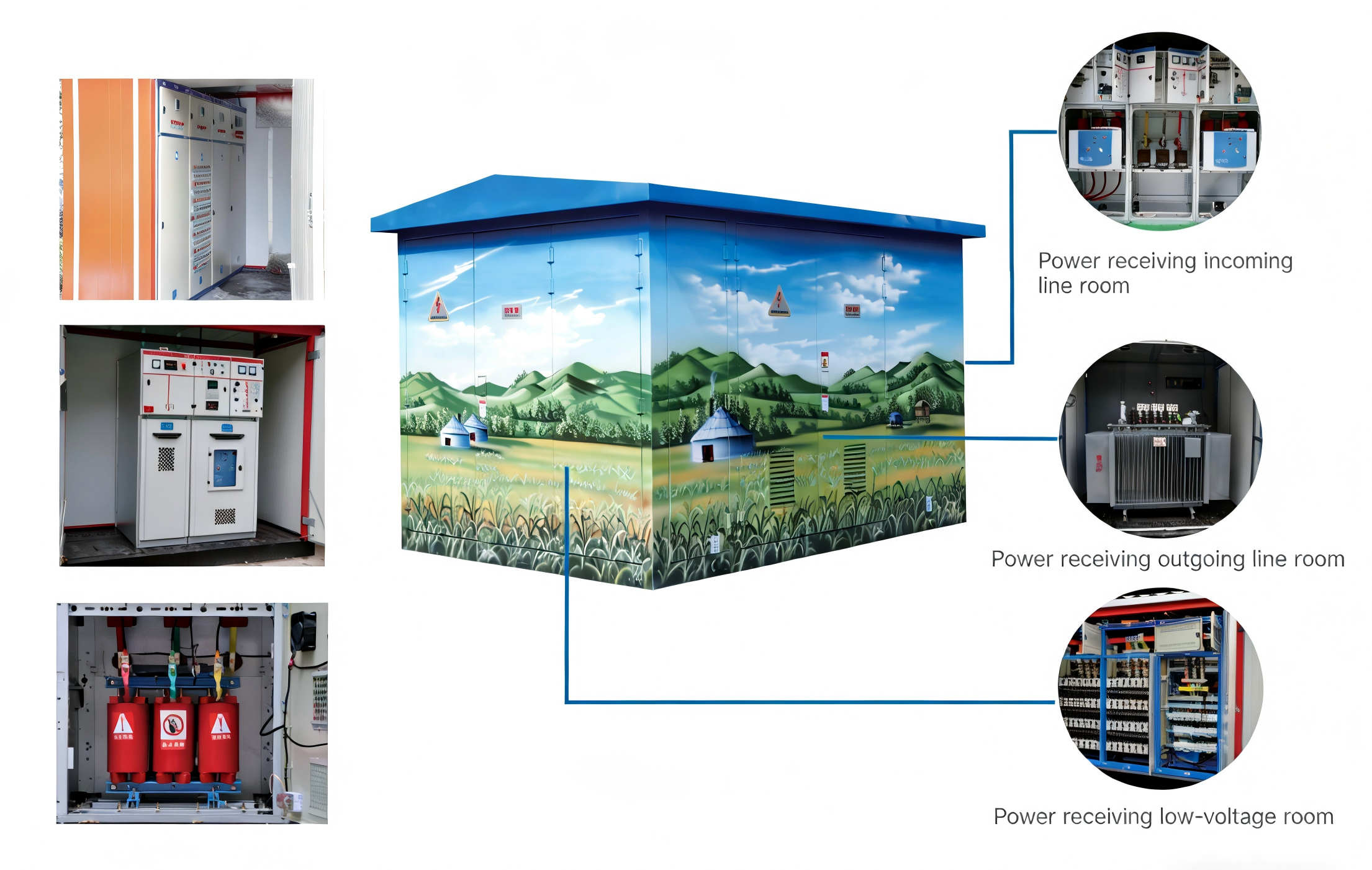
- Integration of high-voltage switchgear, transformer and low-voltage switchgear, with strong integrity;
- Complete high and low voltage protection, safe and reliable operation, simple maintenance;
- Small floor area, low investment cost, short production cycle and convenient movement;
- Flexible wiring schemes;
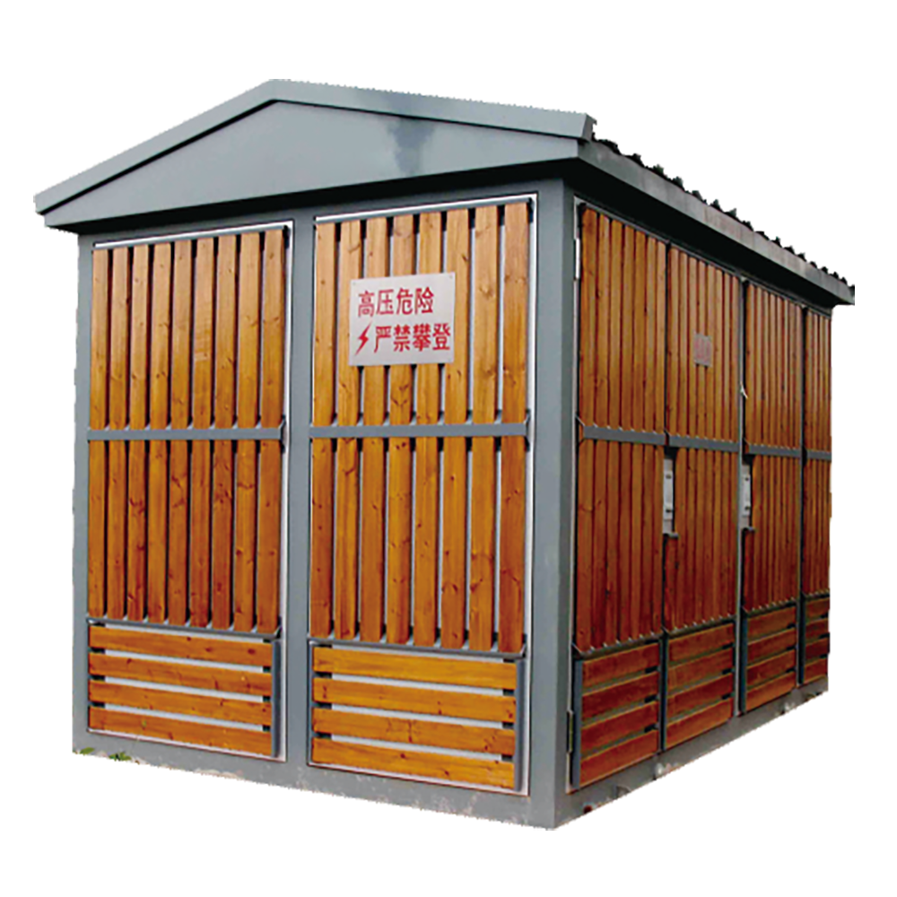
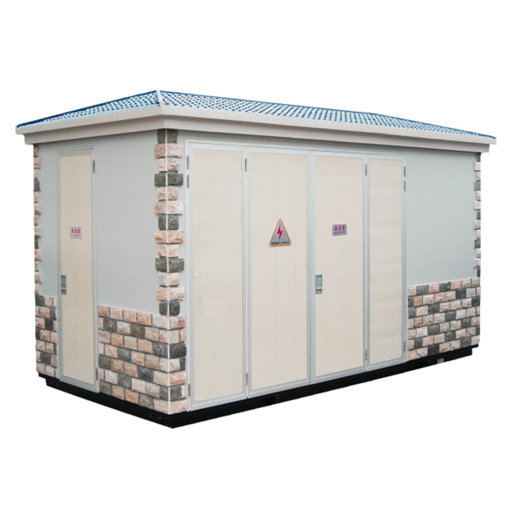
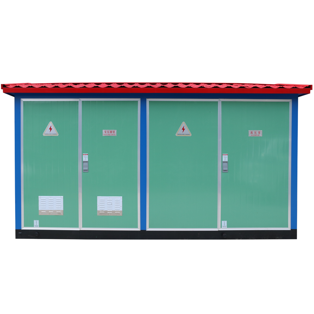
- Unique structure: special honeycomb structure double-layer (composite board) shell is firm, heat insulation and good ventilation, beautiful appearance, high protection level; shell materials can be selected from stainless steel alloy, aluminum alloy, cold-rolled plate, color steel plate;
- Various types: universal type, villa type, compact type and other styles;
- Automatic line feeder terminal (FTU) can be equipped in the high-voltage ring network to realize reliable detection of short-circuit and single-phase grounding faults, with "four remote" functions, convenient for power grid automation upgrade.
5. Transformer & High/Low Voltage Side Introduction
Transformer: The intelligent integrated substation adopts low-loss, oil-immersed, fully sealed S9, S10, S11 series transformers, and can also select resin insulation or NOMEX low-loss environmental protection dry-type transformers. The bottom can be equipped with a trolley for convenient in and out of the transformer.
High Voltage Side: The high-voltage side of the intelligent integrated substation generally adopts load switch + fuse combined protector. When the fuse is blown, the three-phase linkage tripping is realized. The load switch can be selected from pneumatic, vacuum, sulfur hexafluoride and other types, and can be equipped with electric operating mechanism to realize automation upgrade; the fuse is high-voltage limit fuse with striker, reliable action and large breaking capacity. For transformers above 800kVA, QCE4, QCE2, QCE1 and other vacuum circuit breakers can be selected for protection (main technical parameters are shown in the table below).
Low Voltage Side: The low-voltage main switch adopts universal or intelligent circuit breaker with selective protection; the outgoing line adopts new type of switch cabinet with small volume and good arc extinguishing performance, up to 30 circuits; the intelligent automatic reactive power compensation device is equipped, with contactor and contactless two switching modes for users to choose.
6. Executive Standards
- GB/T17467-1998 《High/Low Voltage Prefabricated Substation》
- DL/T537-93 《Technical Conditions for 35kV Prefabricated Substation Ordering》
7. Technical Parameters of Load Switch
| No. | Name | Unit | FKN12-12 Load Switch | FZN25-12 Vacuum Load Switch |
|---|---|---|---|---|
| 1 | Rated Voltage | kV | 10 | |
| 2 | Maximum Working Voltage | kV | 12 | |
| 3 | Rated Frequency | Hz | 50 | |
| 4 | Rated Current | A | 630 | |
| 5 | Rated Breaking Current | A | 630 | |
| 6 | Thermal Stable Current (Effective Value) | kA/S | 20/2 | 20/4 |
| 7 | Dynamic Stable Current | kA | 50 | 50 |
| 8 | Short-Circuit Making Current (Peak Value) | kA | 50 | 50 |
| 9 | Full Load Breaking Times | times | 20 | 1000 |
| 10 | Mechanical Life | times | 2000 | 10000 |
| 11 | 1min Withstand Voltage (Phase to Phase & Phase to Ground) | kV | 42 | 42 |
| 12 | Lightning Impulse Withstand Voltage | kV | 75 | 75 |
Note: Determined by whether the arrester is installed, N means no needle, A means with needle.
8. Main Technical Parameters
| Foreign Model | Domestic Model | Rated Voltage (kV) | Breaking Current (A) | Breaking Current (kA) | Fuse Rated Current (A) |
|---|---|---|---|---|---|
| SDL※8J | XRN1-12 | 12 | 40 | 31.5 | 6.3,10,16,20,25,31.5,40 |
| SFL※J | 12 | 100 | 31.5 | 50,63,71,80,100 | |
| SKL※8J | 12 | 125 | 31.5 | 125 |
Note: Determined by the installation impact needle, N is without needle, A is with needle.
| Serial No. | Circuit Breaker Type | Circuit Breaker Rated Current (A) | Breaking Capacity(kA, AC380V) |
|---|---|---|---|
| DW15-630 | Electromagnetic/Electronic Type | 315,400,630 | 40 |
| DW15-1600 | 1600 | 50 | |
| DW15-2000 | 1600,2000 | 60 | |
| CV1-2000 | Intelligent Type | 630,800,1000,1250,1600,2000 | 65(80) |
| CV1-3200 | 2000,2500,3200 | 100 |
9. Installation, Use and Maintenance
For the intelligent integrated substation, in addition to the various regulations to be implemented by the electric power department in terms of acceptance, handover test, operation and maintenance, the following matters should be noted:
- The product shall be carefully inspected according to the relevant specifications upon receipt. For products not installed immediately, they shall be stored in an appropriate place in accordance with the normal service conditions.
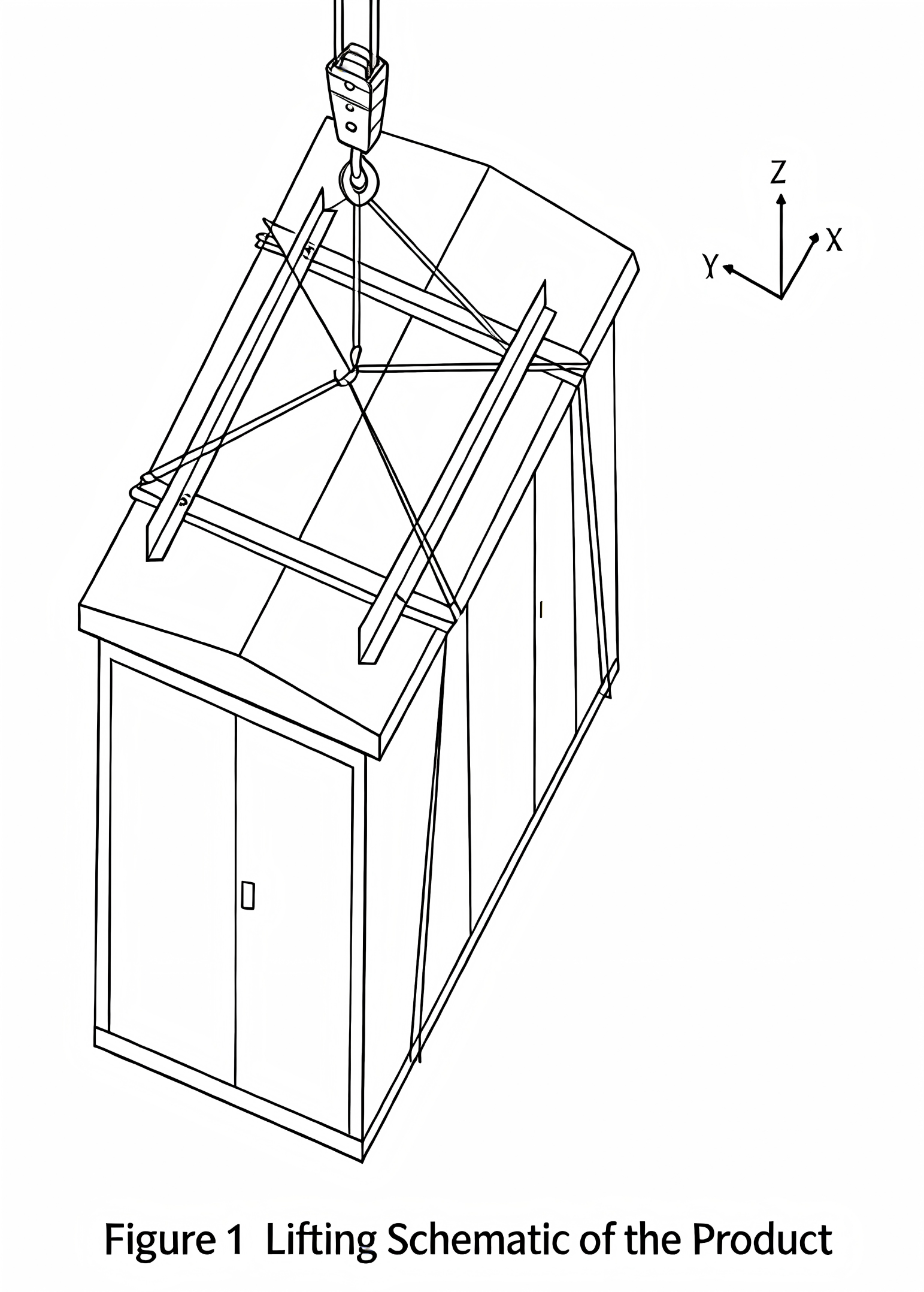
- The product shall be hoisted with special lifting tools as shown in Figure 3.
- The product shall be placed on a pre-built foundation, and then the gap between the product base and the foundation shall be sealed with cement mortar to prevent rainwater from entering the cabinet, and the high and low voltage bottom plates shall be connected to the high and low voltage cables.
- After the product is in place, it shall be reliably grounded; the two main grounding terminals on the substation channel steel.
- The neutral point of the transformer, the outer shell, the lower head of the lightning arrester, etc. shall be respectively grounded by the installation department, and all grounding shall share a set of grounding device with the grounding resistance less than 4 ohms, and the number of grounding leads from the grounding grid to the product shall not exceed two.
After the installation and maintenance of the substation are completed, the following inspections and tests shall be carried out before commissioning:
- Whether the substation is clean inside;
- Whether the operating mechanism is flexible;
- Whether the opening and closing of the main electrical appliances are flexible and reliable;
- Whether the opening and closing of the auxiliary contacts of the circuit are reliable and accurate;
-
Whether the meters and relay actions are accurate and error-free;
- Whether the ratio and wiring polarity of instruments and transformers are correct;
- Whether all electrical installation screws are tightened, and the installation is firm and reliable;
- Whether the busbar connection is good, and the supporting insulators and clamps are installed reliably;
- Whether the setting value of the electrical appliance meets the requirements, and the fuse core specification is correct;
-
Whether the joints of the main circuit and auxiliary circuit meet the requirements of the electrical schematic diagram.
Maintenance
- All components in the substation shall be maintained in accordance with their respective technical requirements;
- If the selected transformer is oil-immersed, an oil sample analysis and inspection shall be carried out at least once a year in accordance with the regulations;
- The high-voltage switchgear in operation shall be inspected for the wear degree of the contact head and arc extinguishing device after 20 times of rated load or 2000 times of no-load closing and opening operations, and replaced in time if abnormalities are found;
- When the low-voltage switchgear trips automatically, the cause shall be analyzed and checked, and the fault shall be eliminated before restarting;
- The lightning arrester shall undergo a preventive test before the arrival of the thunderstorm season every year;
* The product is equipped with packing list, certificate of conformity, installation and operation instructions, electrical wiring diagram, instructions for the main equipment adopted by the product, key operation tools and spare parts provided according to the agreement.
10. Substation Structure Diagram
11. Ordering Notes
The following information must be provided when placing an order:
- Type and quantity of transformer;
- High and low voltage primary wiring scheme and models and parameters of main components;
- Material and color of the outer shell.

11-20-10kV Epoxy Cast Dry-Type Transformer")
-12 Outdoor High-Voltage Vacuum Circuit Breaker / Primary and Secondary Integration (with Directional Judgment)")


-12 Indoor High-voltage Vacuum Circuit Breaker / Drawout Type")