 Yongce Group Co., Ltd.
Complete Product Introduction
1. Product Brief Introduction
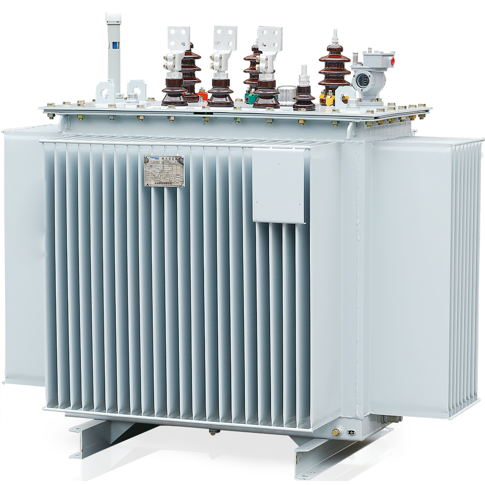
The S13-M three-phase wound core hermetically sealed distribution transformer covers a capacity range of 30kVA-1000kVA with 15 varieties in total. The iron core adopts a three-phase three-column type outer winding structure with a high degree of mechanization. The low-voltage coil is wound on the iron core column with tight winding and solid coil arrangement. The main technical and economic indicators have reached the international professional level of similar products.
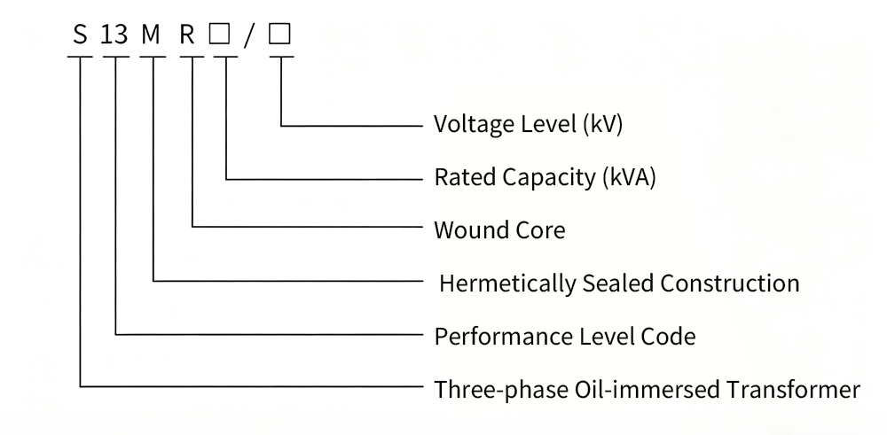
2. Model Meaning & Explanation
The coding of the product model contains the core structural characteristics and parameter information of the transformer. The specific meaning of each part of the model is as follows:
3. Executive Standards & Specifications
The design, production and inspection of the product are strictly in accordance with the following national and international standards to ensure product quality and performance compliance:
- GB1094.1-2013 Power Transformers - Part 1: General
- GB1094.3-2003 Power Transformers - Part 3: Insulation Levels, Dielectric Tests and External Clearances in Air
- GB/T1094.4-2005 Power Transformers - Part 4: Guide to Lightning Impulse and Switching Impulse Testing
- GB1094.5-2008 Power Transformers - Part 5: Ability to Withstand Short Circuit
- GB/T6451-2008 Technical Parameters and Requirements for Three-Phase Oil-Immersed Power Transformers
- International Standard IEC76 Power Transformers
- GB/T25289-2010 Technical Parameters and Requirements for 20kV Oil-Immersed Power Distribution Transformers
4. Performance Characteristics
- Compared with the "9" series transformers, this product has an average reduction of 30% in no-load loss. In comparison with JB/T1088-1999 standard, it features lower noise (reduced by 7dB), and the temperature rise limit of oil surface and high-low voltage windings is about 20K-13K lower, with strong overload capacity.
- High short-circuit resistance and reliable operation performance, with overall performance reaching advanced international levels.
- Low no-load loss and low noise meet the requirements of energy conservation and environmental protection.
- Excellent thermal stability and overload capacity to adapt to complex power grid operating conditions.
5. Structural Characteristics
The product adopts a scientific and reasonable structural design to ensure stable operation and long service life, with the following structural characteristics:
- Core: Adopts three-phase three-column inner and outer winding structure, with multi-stage elliptical cross-section of core columns. The core is annealed in vacuum after manufacturing to eliminate stress; the clamping parts of the core are grooved, and the pull rods and clamping pieces are insulated; the surface of the core is coated with special paint to ensure no deformation and rust of the core.
- Windings and Tank Body: The low-voltage winding adopts four-layer or double-layer cylindrical type (for 500kVA and below) or continuous type (for 630kVA and above) with 1-6 parallel conductors; the conductors are brazed with oxygen-free copper; the inter-turn and inter-layer insulation of the low-voltage winding is bonded with grid points; the oil passage between high-voltage radial oil passages and high-low voltage main air passages adopts strip structure; the iron yoke insulation and trapezoidal cushion blocks are integrated to make the winding evenly stressed.
- The tank body adopts a new type of steel plate positioning structure with longitudinal and transverse positioning to ensure the tank body is stable without displacement.
- Tank: Adopts corrugated tank hermetically sealed structure, which is maintenance-free without oil leakage.
6. Main Technical Parameters
| Rated Capacity (kVA) | Voltage Combination (kV) | Connection Symbol | No-load Loss (W) | Load Loss (W) | Impedance Voltage (%) | No-load Current (%) | ||
|---|---|---|---|---|---|---|---|---|
| High Voltage | Tap (%) | Low Voltage | ||||||
| 30 | 6, 6.3, 10, 10.5, 11 | ±5% or ±2×2.5% | 0.4 | Yyn0 or Dyn11 | 100 | 600/630 | 4.0 | 0.80 |
| 50 | 130 | 870/910 | 0.75 | |||||
| 63 | 150 | 1040/1090 | 0.70 | |||||
| 80 | 180 | 1250/1310 | 0.70 | |||||
| 100 | 200 | 1500/1580 | 0.65 | |||||
| 125 | 240 | 1800/1890 | 0.65 | |||||
| 160 | 280 | 2200/2310 | 0.60 | |||||
| 200 | 340 | 2600/2730 | 0.60 | |||||
| 250 | 400 | 3050/3200 | 0.50 | |||||
| 315 | 480 | 3650/3830 | 0.45 | |||||
| 400 | 570 | 4300/4520 | 0.40 | |||||
| 500 | 680 | 5100/5410 | 0.40 | |||||
| 630 | 810 | 6200 | 4.5 | 0.40 | ||||
| 800 | 980 | 7500 | 0.40 | |||||
| 1000 | 1150 | 10350 | 0.30 | |||||
Notes:
1. The load loss values below the oblique line in the table are applicable to products with Dyn11 connection group.
2. For technical parameters of 10kV distribution transformers with larger capacities, please consult our company for external dimensions and weight data.
3. Transformers with customized voltage combinations, winding impedance and connection modes can be provided according to user requirements.
4. The weight and external dimension data in the table are for reference only, and no separate notice will be given if there are changes.
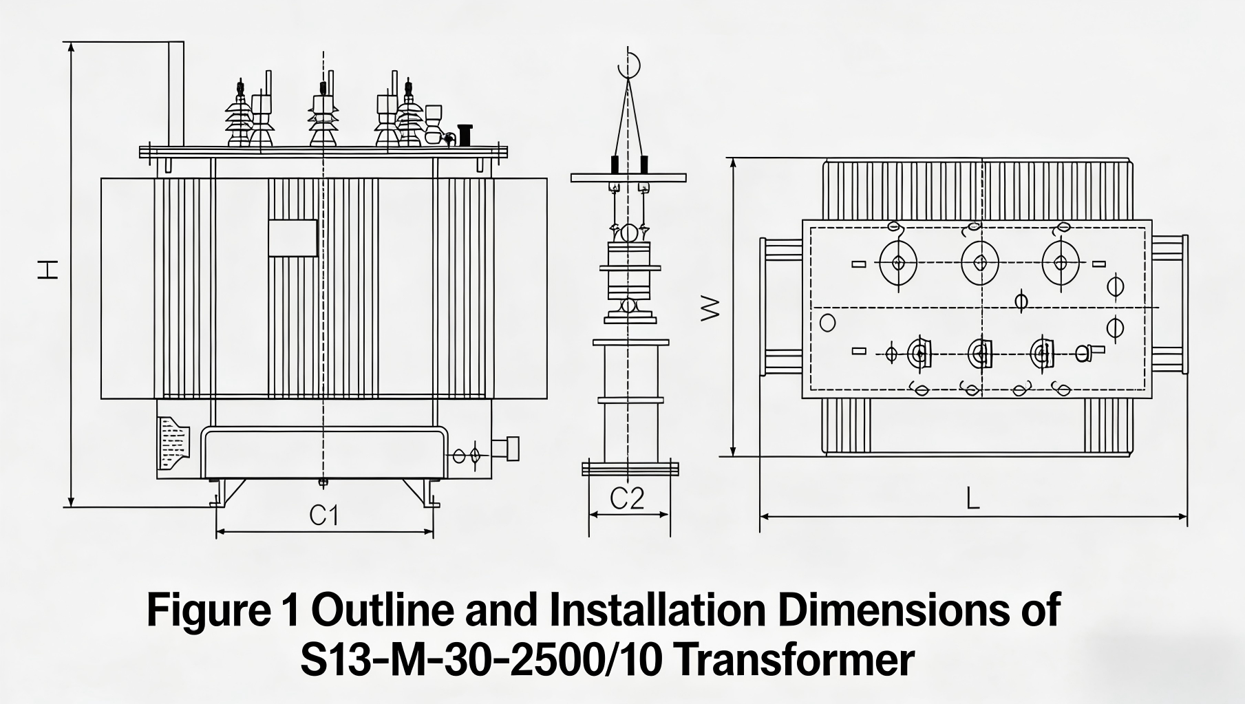
7. Overall Dimensions & Installation Dimensions
| Serial No. | Capacity (kVA) | Product Dimensions | Footing | |||
|---|---|---|---|---|---|---|
| Length (mm) | Width (mm) | Height (mm) | Horizontal (mm) | Vertical (mm) | ||
| 1 | 30 | 725 | 510 | 955 | 400 | 400 |
| 2 | 50 | 770 | 560 | 1020 | 400 | 400 |
| 3 | 80 | 790 | 710 | 1035 | 550 | 550 |
| 4 | 100 | 840 | 595 | 1140 | 550 | 550 |
| 5 | 125 | 870 | 615 | 1145 | 550 | 550 |
| 6 | 160 | 910 | 725 | 1185 | 550 | 550 |
| 7 | 200 | 920 | 715 | 1255 | 550 | 550 |
| 8 | 250 | 960 | 775 | 1285 | 660 | 660 |
| 9 | 315 | 1010 | 820 | 1325 | 660 | 660 |
| 10 | 400 | 1230 | 740 | 1400 | 660 | 660 |
| 11 | 500 | 1320 | 810 | 1460 | 660 | 660 |
| 12 | 630 | 1420 | 875 | 1500 | 660 | 660 |
| 13 | 800 | 1560 | 1080 | 1525 | 820 | 820 |
| 14 | 1000 | 1670 | 1195 | 1615 | 820 | 820 |
| 15 | 1250 | 1720 | 1245 | 1700 | 820 | 820 |
| 16 | 1600 | 1820 | 1380 | 1800 | 820 | 820 |
| 17 | 2000 | 1930 | 1380 | 1800 | 820 | 820 |
| 18 | 2500 | 1990 | 1380 | 1760 | 820 | 820 |
8. Ordering Notes
When placing an order, the following information must be provided to ensure accurate product customization and delivery:
- Product model number
- Rated capacity
- High and low voltage rated voltage and high voltage tapping range
- Number of phases, frequency
- Connection group symbol


10-10kV Environment-friendly Dry-type Transformer")


