 Yongce Group Co., Ltd.
Complete Product Introduction
1. Product Overview
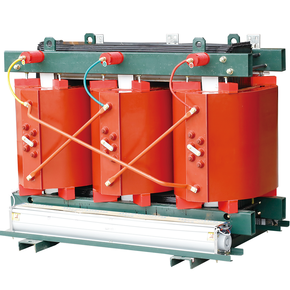
The SC(B)11-30~2500/20-10 dry-type transformer is a new generation of power distribution transformer adopting vacuum casting molding process with epoxy resin as the main insulation material. It covers a capacity range of 50kVA to 3150kVA, featuring excellent insulation performance, fire and explosion proof, low loss, low noise and maintenance-free characteristics, and is widely used in various high-fire-safety-requirement power distribution systems.
2. Scope of Application
This product has a wide range of applications, and is particularly suitable for places with high fire protection requirements, such as mines, oil fields, subways, power plants, schools, hospitals, commercial centers, high-rise buildings and all indoor power distribution systems.
3. Model Interpretation
The product model coding contains the core structural characteristics and parameter information of the transformer. The specific meaning of each part of the model is as follows:
11 Model Explanation")
Model Breakdown:
S - Three-phase
C - Cast resin insulation
(B) - Enclosed type (optional)
11 - Design sequence number
□ - Rated capacity (kVA)
20-10 - High voltage side voltage level (kV)
4. Working Conditions
The transformer can operate reliably under the following environmental and working conditions to ensure stable performance and long service life:
- Installation altitude: Not exceeding 1000m;
- Power supply voltage waveform: Approximately sinusoidal;
- Symmetry of multi-phase power supply voltage: The power supply voltage connected to the multi-phase transformer shall be approximately symmetric.
- Ambient temperature: Maximum +40℃; Maximum daily average +30℃; Maximum annual average +20℃; Minimum -25℃ (applicable to indoor transformers).
5. Executive Standards
The design, production and inspection of the product strictly comply with the following national and international standards to ensure the compliance of product quality and performance:
- GB1094.1-2013 Power Transformers - Part 1: General Requirements
- GB1094.3-2003 Power Transformers - Part 3: Insulation Levels, Dielectric Tests and External Clearances in Air
- GB1094.11-2007 Power Transformers - Part 11: Dry-type Transformers
- GB/T10228-2015 Technical Requirements for Dry-type Power Transformers
- International Standard IEC 60076 Power Transformers
6. Performance Features
- High insulation performance: Epoxy resin casting insulation structure, with excellent resistance to partial discharge, moisture resistance and aging resistance, partial discharge quantity ≤5pc.
- Fire and explosion proof: No oil in the whole machine, no fire, explosion and oil leakage risks, high safety performance. It can be directly installed in the load center.
- Low loss and energy saving: The no-load loss is reduced by more than 30% compared with the traditional dry-type transformer, and the operation efficiency is high.
- Low noise: The noise level is 5-8dB lower than the national standard, which meets the environmental protection requirements of urban power distribution.
- Maintenance-free: Sealed structure design, no need for regular oil change and maintenance, reducing operation and maintenance costs.
- Strong overload capacity: It can adapt to the complex load changes of the power grid and has good thermal stability. It can operate normally at 100% humidity and be put into operation without pre-drying after shutdown.
7. Structural Features
- Core: Adopts high magnetic permeability, high-quality grain-oriented cold-rolled silicon steel sheets, assembled with 45° full-step lap joint. The core uses a special square tube pull plate structure, the core columns are bound with insulating tape, and the surface of the core is coated with special resin to prevent moisture and rust, which effectively reduces no-load loss, no-load current and core noise.
- Foil Winding: The low-voltage winding is made of integral copper foil, wound on a special low-voltage foil winding machine together with Class F insulation. The foil winding well solves the prominent problems of short-circuit stress, voltage imbalance, poor heat dissipation, existence of winding helix angle and unstable manual welding quality in low-voltage, large-current winding products. At the same time, the end of our company's winding is sealed with resin, cured and formed, which is moisture-proof and anti-pollution.
- Temperature Control Device: The transformer adopts BWDK series signal thermometer, and the temperature measuring elements are embedded in the upper part of the low-voltage winding, which can automatically detect and cyclically display the operating temperature of the three-phase windings. It also has over-temperature alarm and trip functions.
- Voltage Conversion: The connecting pieces can realize 10kV and 20kV voltage conversion in different positions, which are respectively suitable for 10kV and 20kV system voltage requirements.
- Frame and Shell: The transformer is equipped with a steel frame, and the windings and core are fixed on the frame to ensure structural stability; the shell can be configured with a protective cover with ventilation holes according to user requirements, which has the functions of dust prevention, protection and noise reduction.
8. Main Technical Parameters
| Rated Capacity (kVA) | Voltage Combination (kV) | Connection Symbol | Loss (kW) | No-load Current (%) | Short-circuit Impedance (%) | |||
|---|---|---|---|---|---|---|---|---|
| High Voltage | High Voltage Tap Range | Low Voltage | Load | No-load | ||||
| 50 |
20,22 24/10 11,12 |
±5% ±2×2.5% |
0.4 | Dyn11 | 1.23 | 0.3 | 2.3 | 6 |
| 100 | 1.98 | 0.47 | 1.9 | |||||
| 160 | 2.46 | 0.58 | 1.7 | |||||
| 200 | 2.93 | 0.64 | 1.6 | |||||
| 250 | 3.4 | 0.73 | 1.5 | |||||
| 315 | 4.06 | 0.84 | 1.4 | |||||
| 400 | 4.82 | 1.0 | 1.3 | |||||
| 500 | 5.76 | 1.17 | 1.3 | |||||
| 630 | 6.8 | 1.32 | 1.2 | |||||
| 800 | 8.22 | 1.52 | 1.1 | |||||
| 1000 | 9.73 | 1.79 | 1.0 | |||||
| 1250 | 11.48 | 2.06 | 1.0 | |||||
| 1600 | 13.79 | 2.41 | 0.9 | |||||
| 2000 | 16.29 | 2.8 | 0.9 | |||||
| 2500 | 19.27 | 3.34 | 0.8 | |||||
| 3150 | 23.0 | 3.9 | 0.7 | |||||
Notes:
1. The load loss is measured at 120℃ of winding average temperature (converted from 75℃ data).
2. For transformers with Dyn11 connection group, the loss parameters can be adjusted according to user requirements.
3. Customized technical parameters can be provided according to user special requirements.
9. Overall & Installation Dimensions

| Serial No. | Capacity (kVA) | Product Dimensions (mm) | Footing Dimensions (mm) | Remarks | |||
|---|---|---|---|---|---|---|---|
| Length | Width | Height | Horizontal | Vertical | |||
| 1 | 100 | 970 | 690 | 955 | 550 | 600 | |
| 2 | 125 | 985 | 745 | 1080 | 660 | 660 | |
| 3 | 160 | 990 | 750 | 1080 | 660 | 660 | |
| 4 | 200 | 990 | 755 | 1090 | 660 | 660 | |
| 5 | 250 | 1040 | 780 | 1030 | 660 | 660 | |
| 6 | 315 | 1060 | 775 | 1120 | 660 | 660 | |
| 7 | 400 | 1090 | 785 | 1150 | 660 | 660 | |
| 8 | 500 | 1110 | 795 | 1210 | 660 | 660 | |
| 9 | 630 | 1240 | 900 | 1130 | 820 | 820 | |
| 10 | 800 | 1320 | 905 | 1280 | 820 | 820 | |
| 11 | 1000 | 1370 | 925 | 1330 | 820 | 820 | |
| 12 | 1250 | 1420 | 1000 | 1470 | 940 | 940 | |
| 13 | 1600 | 1460 | 1010 | 1570 | 940 | 940 | |
| 14 | 2000 | 1520 | 1150 | 1580 | 1070 | 1070 | |
| 15 | 2500 | 1620 | 1150 | 1700 | 1070 | 1070 | |
10. Ordering Instructions
When placing an order, the following information must be provided to ensure accurate product customization and delivery:
- Product model number
- Rated capacity
- High and low voltage rated voltage and high voltage tapping range
- Number of phases and frequency
- Connection group symbol
 Outdoor High-Voltage Vacuum Circuit Breaker")
-12 Outdoor High-Voltage Vacuum Circuit Breaker / Primary and Secondary Integration (with Directional Judgment)")


 Type Electrical Load Control Metering Cabinet")
