LW□-12 SF6 Circuit Breaker Product Introduction
Product Introduction
1. Product Brief Introduction
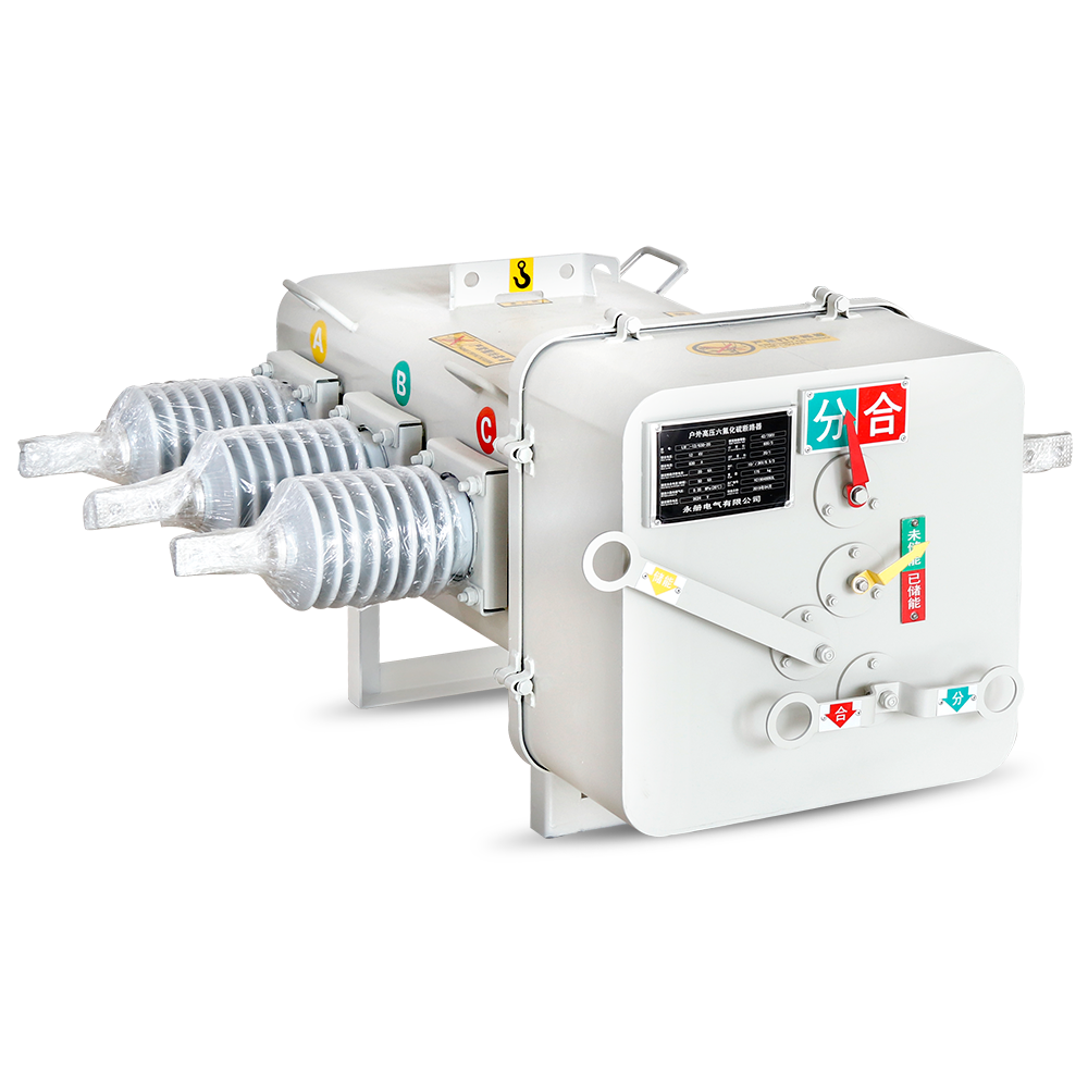
The LW□-12 integrated SF6 circuit breaker (hereinafter referred to as the circuit breaker) is a new type of product developed by our company in accordance with the requirements of the State Grid Corporation of China for integrated pole-mounted switchgear. The circuit breaker complies with the requirements of the State Grid for integrated pole-mounted switchgear, with advantages such as compact structure, reasonable layout, and complete functions. All indicators of the circuit breaker meet the requirements of the integrated pole-mounted switchgear, and have passed the special inspection for integration by China Electric Power Research Institute Co., Ltd. The circuit breaker adopts three-phase protection current transformers, zero-sequence current transformers and zero-sequence voltage sensors with unified parameters, featuring wide measuring range, high measuring accuracy and high reliability. Cooperating with the integrated controller, it can quickly and accurately determine various faults of the line.
2. Operating Conditions
-
Ambient air temperature: -40℃ ~ +40℃;
-
Altitude: not exceeding 3000m;
-
The ambient air may be polluted by dust, smoke, corrosive gases, steam or salt mist, pollution class: IV;
-
Wind speed not exceeding 34m/s (equivalent to 700Pa on the surface of the component);
-
Vibration or shock from outside the switchgear and control equipment is negligible;
-
The peak value of electromagnetic interference induced in the secondary system shall not exceed 1.10kV.
3. Main Technical Parameters
Main Electrical Parameters (Table 1)
|
No.
|
Item
|
Unit
|
Parameter
|
|
01
|
Rated Voltage
|
kV
|
12
|
|
02
|
Rated Frequency
|
Hz
|
50
|
|
03
|
Rated Current
|
A
|
630
|
|
04
|
Rated Short-Circuit Breaking Current
|
kA
|
20
|
|
05
|
Rated Short-Time Withstand Current
|
kA
|
20
|
|
06
|
Rated Duration of Short-Time Withstand Current
|
s
|
4
|
|
07
|
Rated Peak Withstand Current
|
kA
|
50
|
|
08
|
Rated Charging Current
|
A
|
25
|
|
09
|
Rated Operating Sequence
|
-
|
0-0.3s-Close-180s-Open
|
|
10
|
Rated Working Pressure (Gauge Pressure at 20℃)
|
MPa
|
0.35
|
|
11
|
Minimum Working Pressure (Gauge Pressure at 20℃)
|
MPa
|
0.25
|
|
12
|
1min Power Frequency Withstand Voltage (Minimum Working Pressure) - Phase to Phase & Phase to Ground
|
kV
|
42
|
|
12
|
1min Power Frequency Withstand Voltage (Minimum Working Pressure) - Breaker Opening
|
kV
|
48
|
|
13
|
Rated Lightning Impulse Withstand Voltage (Minimum Working Pressure) - Phase to Phase & Phase to Ground
|
kV
|
75
|
|
13
|
Rated Lightning Impulse Withstand Voltage (Minimum Working Pressure) - Breaker Opening
|
kV
|
85
|
|
14
|
Rated Mechanical Stability Times
|
times
|
10000
|
|
15
|
SF6 Gas Annual Leakage Rate
|
-
|
≤0.5%
|
|
16
|
Rated Operating Voltage
|
V
|
DC24
|
Main Mechanical Characteristic Parameters (Table 2)
|
No.
|
Item
|
Unit
|
Parameter
|
|
01
|
Contact Opening Distance
|
mm
|
36-38
|
|
02
|
Contact Overtravel
|
mm
|
20±2
|
|
03
|
Closing Time
|
ms
|
40-80
|
|
04
|
Opening Time
|
ms
|
30-60
|
|
05
|
Closing/Opening Asynchronism
|
ms
|
≤2
|
|
06
|
Final Closing Speed
|
m/s
|
3.2±0.3
|
|
07
|
Final Opening Speed
|
m/s
|
2.6±0.2
|
|
08
|
Main Circuit Resistance
|
μΩ
|
≤120
|
4. Main Structural Features
-
The circuit breaker adopts the arc-extinguishing principle of arc rotation. It utilizes the magnetic field force of the arc current to make the electric arc rotate at high speed along a certain section. Due to the low mass of the arc, during high-speed rotation, the electric arc gradually lengthens and continuously contacts fresh SF6 gas, which is cooled and extinguished. This structural circuit breaker has strong breaking capacity, long electrical life, and will not produce current chopping phenomenon during small current breaking, with advantages such as no overvoltage caused by operation, high reliability.
-
The circuit breaker adopts a small spring operating mechanism, which has the advantages of reliable action, long mechanical life, simple control, etc. The spring operating mechanism can be operated manually and electrically, with manual/electric closing and opening functions, and also has reclosing function.
-
The circuit breaker box is welded with 3mm thick 304 stainless steel, with an airtight structure and a protection grade of not less than IP67. The box is equipped with clear and observable open/close position indicators and energy storage status indicators, which are reliably connected with the operating mechanism and have reliable indication. The box is equipped with lifting handles to avoid pulling the outlet casing.
-
The circuit breaker body is wired with a 26-core aviation socket, and the pin definition complies with the technical requirements of the State Grid for integrated pole-mounted switches.
Built-in three-phase current transformers for the circuit breaker, main parameters (Table 3)
|
No.
|
Item
|
Unit
|
Parameter
|
|
01
|
Rated Current Ratio
|
-
|
600/1, 600/5
|
|
02
|
Accuracy Class
|
class
|
0.5/5P10
|
|
03
|
Polarity
|
-
|
Additive Polarity
|
|
04
|
Rated Burden
|
VA
|
1, 2.5
|
Built-in zero-sequence current transformer in the circuit breaker, main parameters (Table 4)
|
No.
|
Item
|
Unit
|
Parameter
|
|
01
|
Rated Current Ratio
|
-
|
20/1
|
|
02
|
Accuracy Class
|
class
|
≤3% (1A to rated current of primary input), ≤10% (100A of primary input)
|
|
03
|
Polarity
|
-
|
Additive Polarity
|
|
04
|
Rated Burden
|
VA
|
0.5VA
|
Built-in zero-sequence voltage sensor in the circuit breaker, main parameters (Table 5)
|
No.
|
Item
|
Unit
|
Parameter
|
|
01
|
Transformation Ratio
|
-
|
(10kV/√3)/(6.5V/3)
|
|
02
|
Accuracy Class
|
class
|
≤20 (1.2Um/√3)
|
|
03
|
Insulation Level
|
kV
|
3P
|
|
04
|
Insulation Resistance (After Combination with Switch, Phase to Ground)
|
MΩ
|
>1000
|
|
05
|
Connection Mode
|
-
|
Capacitive Voltage Division
|
5. Overall and Mounting Dimensions

6. Installation and Commissioning
-
Check whether the model and specification of the circuit breaker are consistent with the order contract;
-
Check whether the random documents and accessories are complete;
-
Check whether the surface of the circuit breaker is free of damage, and whether the insulation parts are free of damage and cracks;
-
Check whether the box is deformed and check its airtightness;
-
Check whether the fasteners are loose;
-
Manually and electrically operate the closing and opening of the circuit breaker for 10 times respectively, and the closing and opening should be reliable;
-
Check whether the pressure gauge pointer points to the green area;
-
Conduct inrush current test, and the overcurrent setting value shall meet the requirements;
-
In case of product damage or other doubts, it is recommended to take photos of the damaged situation on site and contact the manufacturer in a timely manner.
7. Installation Requirements
-
For safe lifting, lift horizontally at the four lifting points on the box body;
-
During installation, fix it on the mounting bracket with bolts, and its mounting surface should be flat. If the four mounting points are not on the same plane, add gaskets for adjustment to avoid deformation of the overall structural stress of the circuit breaker;
-
When connecting the circuit breaker with the busbar, do not subject the terminal of the circuit breaker to permanent tension, compression and torsion;
-
After installation, inspect the circuit breaker and clean it.
8. Maintenance and Upkeep
-
The circuit breaker should be inspected regularly and the dirt on the surface of the insulation parts should be removed;
-
Regularly check whether the pressure gauge pointer is in the green area. If the pressure gauge pointer is in the red area, contact the manufacturer for maintenance in a timely manner;
-
For places with frequent operation, attention should be paid to the contact wear, and the circuit breaker shall not be used continuously beyond the allowable breaking times and mechanical life of the circuit breaker;
-
Notes: During maintenance, the circuit breaker should be in the unenergized, open state, with all power sources cut off. The energy storage and closing state springs accumulate energy, and carelessness during maintenance may cause mechanical movement and injury to personnel;
-
Maintenance should be carried out by professional personnel;
-
After maintenance, especially after replacing vulnerable parts or readjusting, the mechanical characteristics of the switch should be tested to meet the technical conditions.
 Yongce Group Co., Ltd.
")

-12G Series Side-mounted Solid-sealed High-voltage Vacuum Circuit Breaker")

 Armored Drawout AC Metal-Clad Switchgear")
