Yongce Group Co., Ltd.
Product Introduction
1. Product Brief Introduction
The XGN15-12 unit type AC metal enclosed ring network switchgear (hereinafter referred to as the ring network cabinet) is a high-voltage electrical equipment developed by our company by introducing advanced foreign technology and in accordance with domestic power grid and urban network transformation requirements. Its main components such as main switch, operating mechanism and metal parts are original imported products of ABB company, and the original technical performance meets the standards of GB/T3906 and IEC62271-200 of the People's Republic of China. It can also be assembled with ABB original AD/SF6 load break switch and fuse combination electrical appliance according to user requirements. Its operation mode is divided into manual and electric types.
The cabinet body is formed by welding 2mm thick aluminum-zinc plate (or cold-rolled plate after plastic spraying), and has two pressure relief holes after assembly, one for the incoming line chamber and the other for the load break switch/busbar chamber. This structure can maximize personal safety and make the equipment safe and reliable in installation and operation.
The XGN15-12 unit type AC metal enclosed ring network switchgear is suitable for 50Hz, 12kV power network, used for the acceptance and distribution of electric energy. The built-in main switch of the cabinet is SF6 switch.
2. Model Meaning & Explanation
The coding of the product model contains the core structural characteristics and parameter information of the ring network cabinet. The specific meaning of each part of the model is as follows: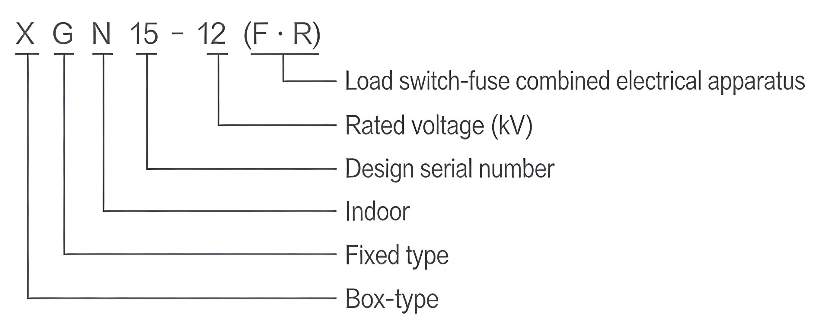
- X: Fixed type
- G: Cabinet type
- N: Indoor type
- 15: Serial number
- 12: Rated voltage (kV)
- (F·R): Load break switch + fuse combination electrical appliance
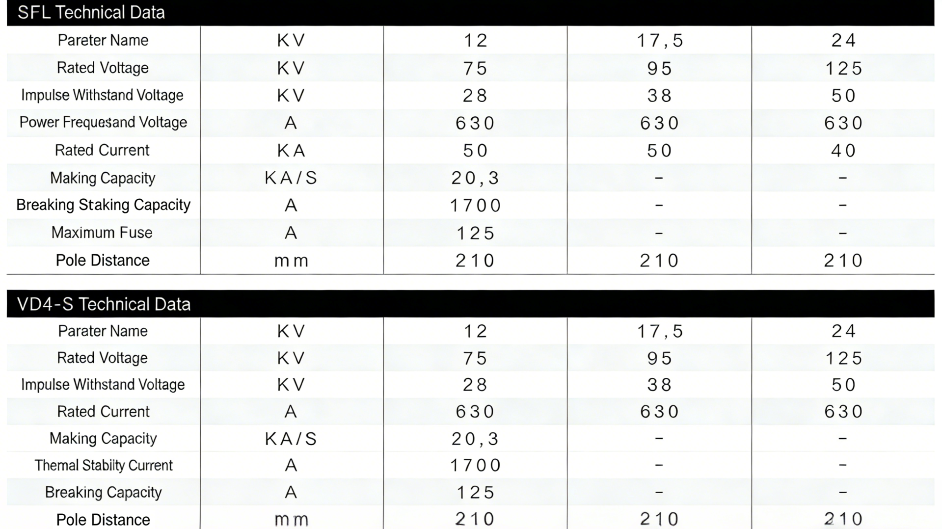
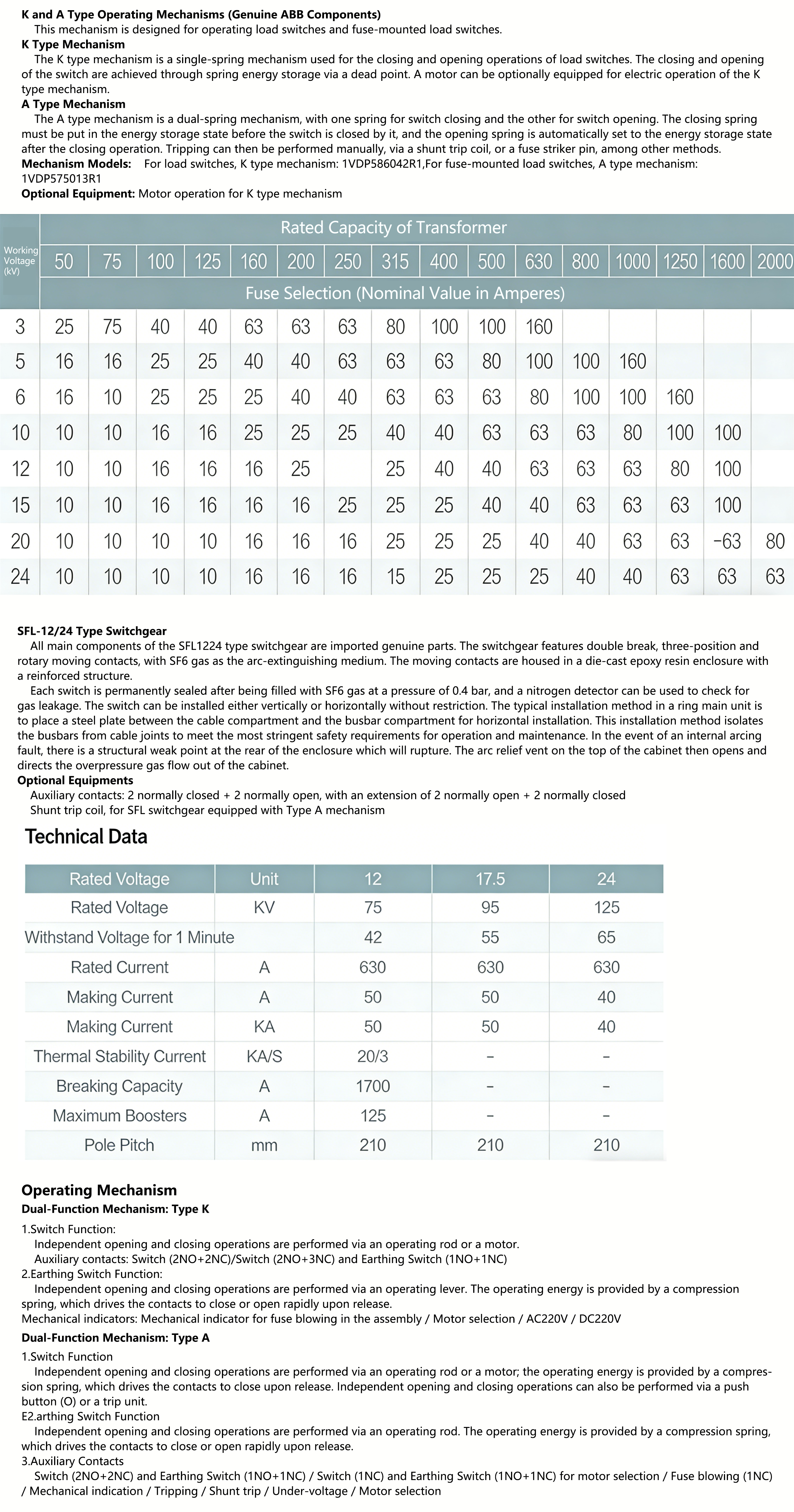
3. Main Technical Parameters of XGN15-12 Ring Network Cabinet
| Serial No. | Name | Unit | Value |
|---|---|---|---|
| 1 | Rated Voltage | kV | 12 |
| 2 | Rated Frequency | Hz | 50 |
| 3 | Main Circuit Rated Current / Maximum Rated Current of Load Break Switch | A | 630, 1250 |
| 4 | Withstand Current of Main Circuit and Earthing Circuit | kA | 20, 3 |
| 5 | Short-time Withstand Current of Main Circuit and Earthing Circuit | kA | 50 |
| 6 | Closing and Making Current of Load Break Switch | kA | 50 |
| 7 | Maximum Breaking Capacity of Load Break Switch | times | 100 |
| 8 | Short-circuit Breaking Current of Load Break Switch | kA | 31.5,40 |
| 9 | Rated Transfer Current | A | 630 |
| 10 | New Added Parameter | A | 1600 |
| 11 | Mechanical Life | times | 2000 |
| 12 | 1min Power Frequency Withstand Voltage (Phase to Phase, Phase to Ground / Isolation Port) | kV | 42, 48 |
| 13 | Lightning Impulse Withstand Voltage (Phase to Phase, Phase to Ground / Isolation Port) | kV | 75, 85 |
| 14 | Secondary Circuit Withstand Voltage | kV | 2 |
| 15 | Protection Grade | - | IP3X |
4. Functions and Characteristics
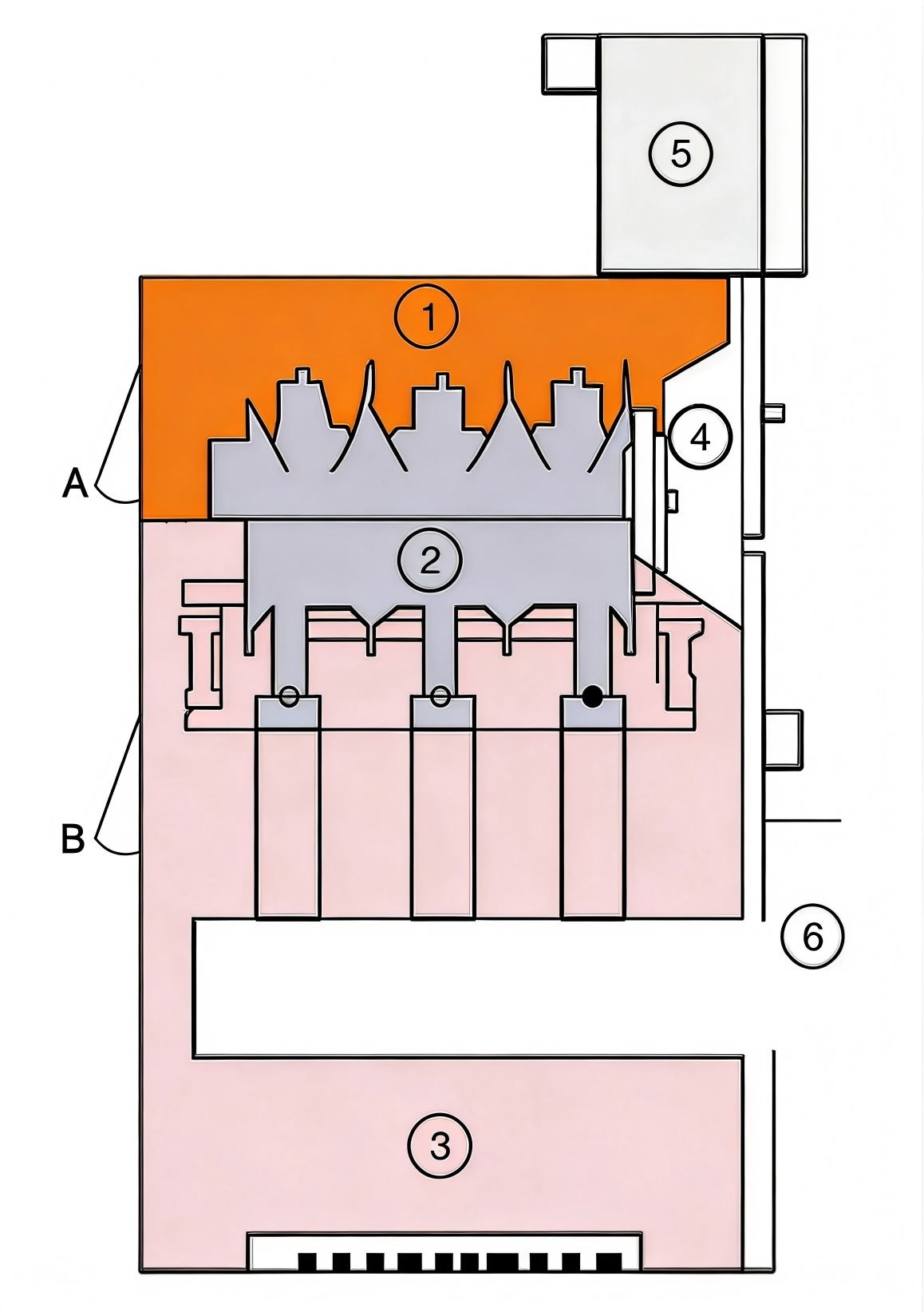
Cabinet Structure
- The ring main unit cabinet is riveted and formed with 2mm-thick aluminized zinc sheet (or cold-rolled sheet after plastic spraying). Two pressure relief holes are arranged at the rear of the cabinet, one for the cable compartment and the other for the load switch/busbar compartment. This structure can maximize the safety of personnel and the reliability of operating equipment.
4.1 Each compartment cell
- Busbar Compartment: Located at the top of the cabinet and connected to adjacent switchgear cabinets.
- Load Switch: It is an independent unit filled with SF₆ gas inside.
- Cable Compartment: Approximately 75% of its space is used for cable connection, fuse, earthing switch installation as well as CT and PT mounting.
- Mechanism Compartment & Interlocking: This compartment houses the operating mechanism, mechanical interlocking, position indicators, auxiliary contacts, trip coils, live line indicators and interlocks.
- Relay Box: Mounted at the top of the cabinet and optional for configuration. The compartment is designed for installing special devices such as meters, relays and motor units.
- Circuit Breaker Compartment: A circuit breaker (SF₆ or vacuum type) can be installed directly below the load switch.
4.2 Pressure Relief
- Upper Pressure Relief:It is designed to release the gas pressure generated by internal arc faults in the busbar and load switch compartment.
- Lower Pressure Relief:It is designed to release the gas pressure generated by internal arc faults in the cable compartment.
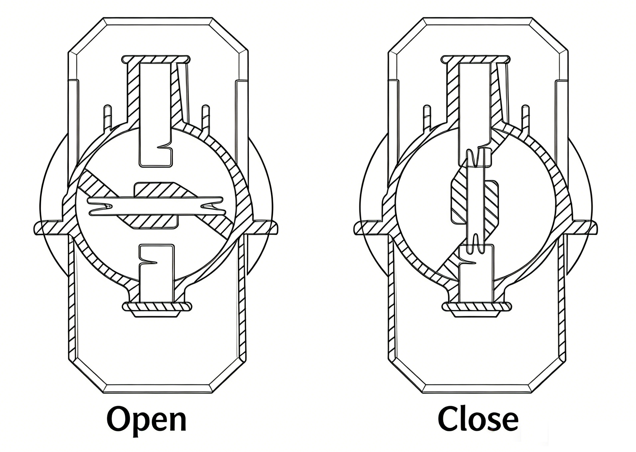
4.3 Type SFL Load Switch (Genuine ABB Component)
- It adopts double-break and rotary moving contacts, with SF₆ gas as the arc-extinguishing medium. Both fixed and moving contacts are enclosed in a moulded epoxy resin housing with a reinforced structure. A transparent thermoformed plastic end cover is fitted at the extension end of the operating shaft, enabling status observation through the cover.
- Each switch is permanently sealed after being filled with SF₆ gas at a pressure of 1.4 bar (SFL stands for "permanently sealed"). A helium detector can be used to check for gas leakage.
- The switch allows both vertical and horizontal installation without restriction. In unit-type cabinets, the typical installation method is horizontal mounting with a steel partition plate installed between the cable compartment and the busbar compartment.
- This mounting method encloses the switch housing in an earthed steel plate and isolates the busbar from cable joints, complying with the most stringent safety requirements for operation and maintenance.
- In the event of an internal arcing fault, a structurally weakened point is provided at the rear of the housing, which will rupture and expel the arc gases out of the switch. Subsequently, the arc relief vent on the top of the cabinet will be forced open and discharge the overpressure gases to the outside of the cabinet.
- Optional Accessories: One set of auxiliary contacts (2 normally closed + 2 normally open) plus an extended set (2 normally open + 2 normally closed), and a shunt trip coil, for Type SFL with Mechanism A.
- Switches with Mechanism K: SFL12/17.5 IVDP575305RI, SFL24K IVDP575304RI
- Switches with Mechanism A: SFL12/17.5 IVDP575303RI, SFL24A IVDP575302RI
4.4 VD4-S Vacuum Circuit Breaker (Genuine ABB Component)
- The Type VD4-S vacuum circuit breaker is specially designed for unit-type switchgear cabinets, with an interrupting capacity sufficient to handle various operating conditions, including the normal switching of equipment or branch networks, as well as short-circuit interruption under special circumstances. It is particularly suitable for networks requiring frequent operation within the working current range.
- Equipped with a spring-operated mechanism, the VD4-S vacuum circuit breaker features a reclosing function (Open - 0.3s - Close-Open - 180s - Close-Open) with reliable operation and a long service life. The entire circuit breaker consists of three vacuum interrupter bottles enclosed in an external resin insulation cylinder, adopting a vertical structure.
- Arc extinction is achieved by the spiral grooves on the arc-extinguishing contacts that force the arc to move. With a minimum static vacuum degree of 10⁻⁴ to 10⁻⁸ bar inside the switch insulation cylinder, a high insulation strength can be obtained despite the relatively small gap between the switch contacts. The arc is extinguished at the first current zero of the short-circuit current.
- The small contact gap, high conductivity of the metal vapor plasma region at the arc voltage drop, and short arcing time result in an extremely low arc energy, which is beneficial for extending the service life of both the contacts and the entire switch.
- Standard Accessories:Manual operation,Electric operation,2 normally open and 2 normally closed auxiliary contacts,Shunt trip with position contacts,Shunt closing coil
- Optional Accessories:S5 or PR512 overcurrent relay,Undervoltage release,Interlock coil
- Circuit Breaker Models:VD41206-20S, VD41706, VD42406
4.5 HAD/US SF6 Circuit Breaker (Genuine ABB Component)
- Type HAD/S SF6 Circuit Breaker Designed exclusively for ring main unit switchgear, it features an interrupting capacity sufficient to handle all operating conditions, including the normal switching of equipment or branch networks and short-circuit interruption under special circumstances. The new-generation HAD incorporates the latest SF6 interruption technology and boasts a simple structure with minimal operating energy requirement. This compact stored-energy operating mechanism enables automatic reclosing operation.
- The special structure of the breaker’s interrupting section provides an extraordinary guarantee for extended electrical service life, while the mechanism delivers a long mechanical service life in operation. The circuit breaker is constructed as a split, independent post-type unit and installed in a vertical configuration. It adopts the self-blast arc extinction principle, utilizing the arc’s own energy to extinguish the arc.
- When the circuit breaker opens, an arc is generated between the fixed and moving contacts in the arc extinguishing chamber. The high temperature and ionization effect of the arc cause a rapid rise in the SF6 gas pressure inside the chamber. As the pressure builds up and the arcing contacts separate gradually, the gas is forcefully ejected through the nozzle out of the arc extinguishing chamber. This action rarefies, cools and interrupts the arc while preventing restriking, which means only a small amount of energy is required for the breaker’s moving parts and further enhances the reliability of long-term operation.
4.6 This switch features numerous advantages:
- Short arcing duration with rapid recovery of insulation strength inside the arc extinguishing chamber.
- Safe and reliable operation guaranteed even in the harshest environments.
- Capable of interrupting low-value inductive and capacitive currents.
- Simplified operating mechanism with fast making and breaking performance and a long mechanical service life.
- Reduced wear on contacts and arc extinguishing chamber, thus extending the electrical service life.
- High allowable operating times with minimal maintenance requirements.
- Lightweight, compact and robust structure.
- Standard Accessories:
Electric operation
Manual operation
Auxiliary contacts (2 NO, 2 NC)
Shunt trip with position contacts
Shunt closing coil
Gas pressure control with signal contacts
- Optional Accessories
S5 solid-state overcurrent relay
PR511 & PR512 overcurrent relays
Undervoltage release
Interlock coil
Model Numbers:HAD120625, HAD120520, HAD170620, HAD170616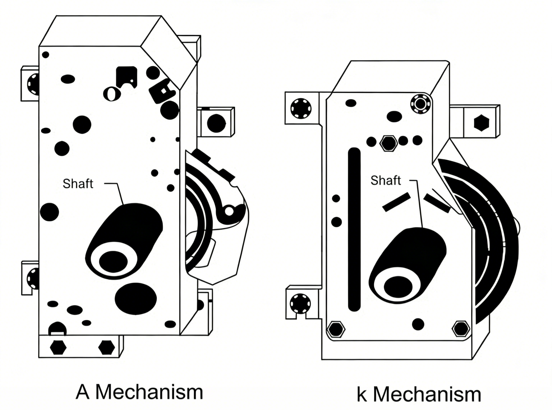
4.7 Type K and A Operating Mechanisms (Genuine ABB Components)
- Operating Mechanisms for Load Switches and Fuse-Integrated Load Switches:This mechanism is designed to operate load switches and fuse-integrated load switches.
- Type K Mechanism:The Type K mechanism is a single-spring mechanism for the closing and opening operations of load switches. The switch’s closing and opening actions are achieved via spring energy storage through a dead point. An electric motor can be optionally fitted to the Type K mechanism for motorized operation.
- Type A Mechanism:The Type A mechanism is a dual-spring mechanism, with one spring for switch closing and the other for switch opening. The closing spring must be charged before the switch is closed, and the opening spring is automatically charged upon the completion of the closing operation. Tripping can thus be initiated manually, via a shunt trip coil, or by a fuse striker pin, among other means.
- Mechanism Model Numbers:For load switches,Type K Mechanism: 1VDP586042R1,For fuse-integrated load switches,Type A Mechanism: 1VDP575013R1
- Optional Equipment:Motorized operation for Type K Mechanism
5. Interlocking
- 1. Only when the grounding switch is in the closed position, the load break switch operation is unlocked; in other cases, it is locked.
- 2. Only when the load break switch is in the open position, the grounding switch operation is unlocked (corrected logic: grounding switch cannot be closed when load break switch is closed).
- 3. Only when the cabinet door is closed and locked, the load break switch can be operated; in other cases, it is locked.
6. Operation
The closing and opening operations of the load break switch are realized by the operating mechanism. When operating manually, the operating handle is rotated clockwise to close the switch and counterclockwise to open the switch; the electric operation is realized by the closing and opening coils. The grounding switch is operated by the operating handle, rotated clockwise to close and counterclockwise to open. All operations are interlocked with each other to improve the safety of power supply and distribution.
7. Overall Dimensions
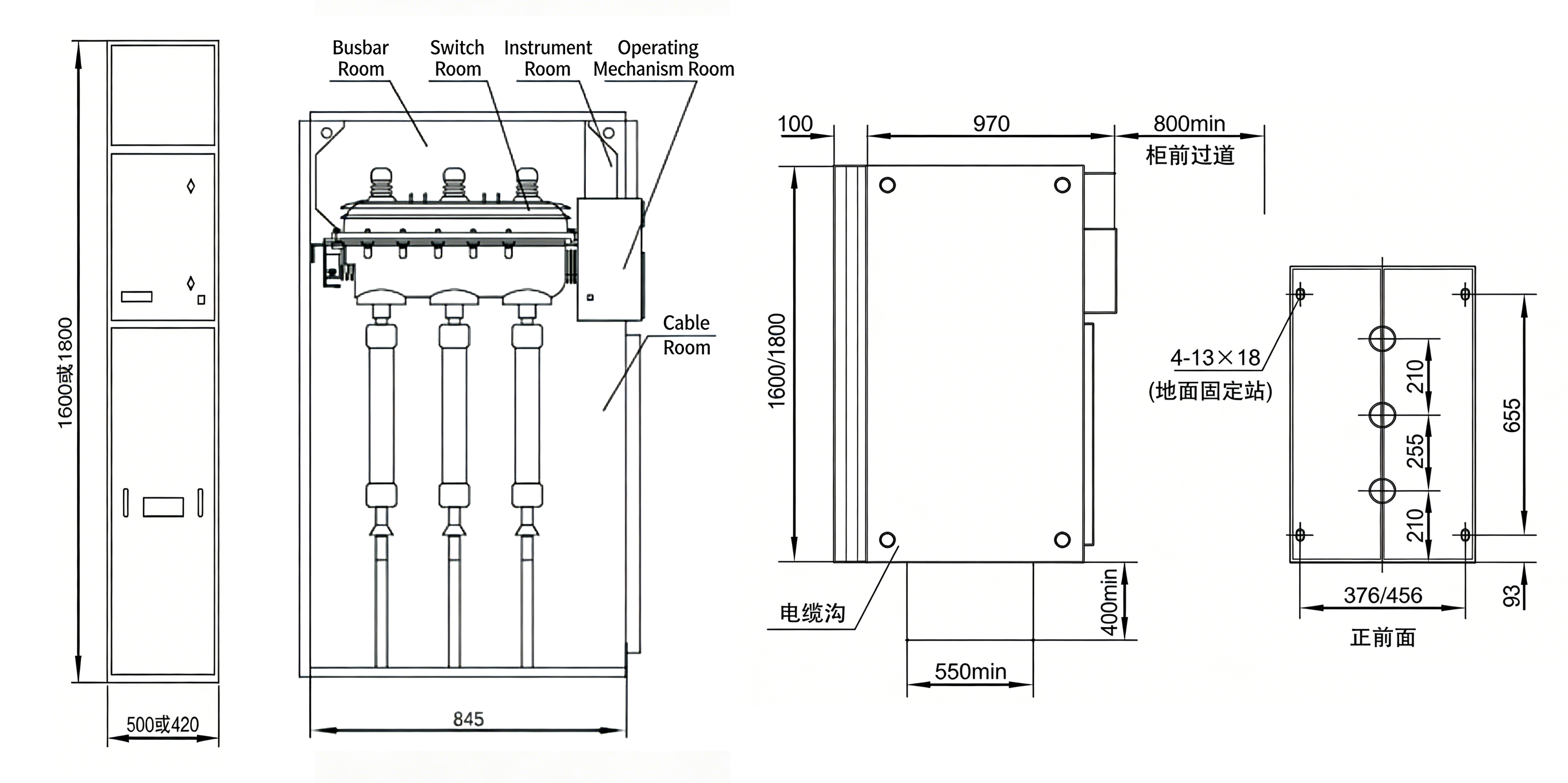
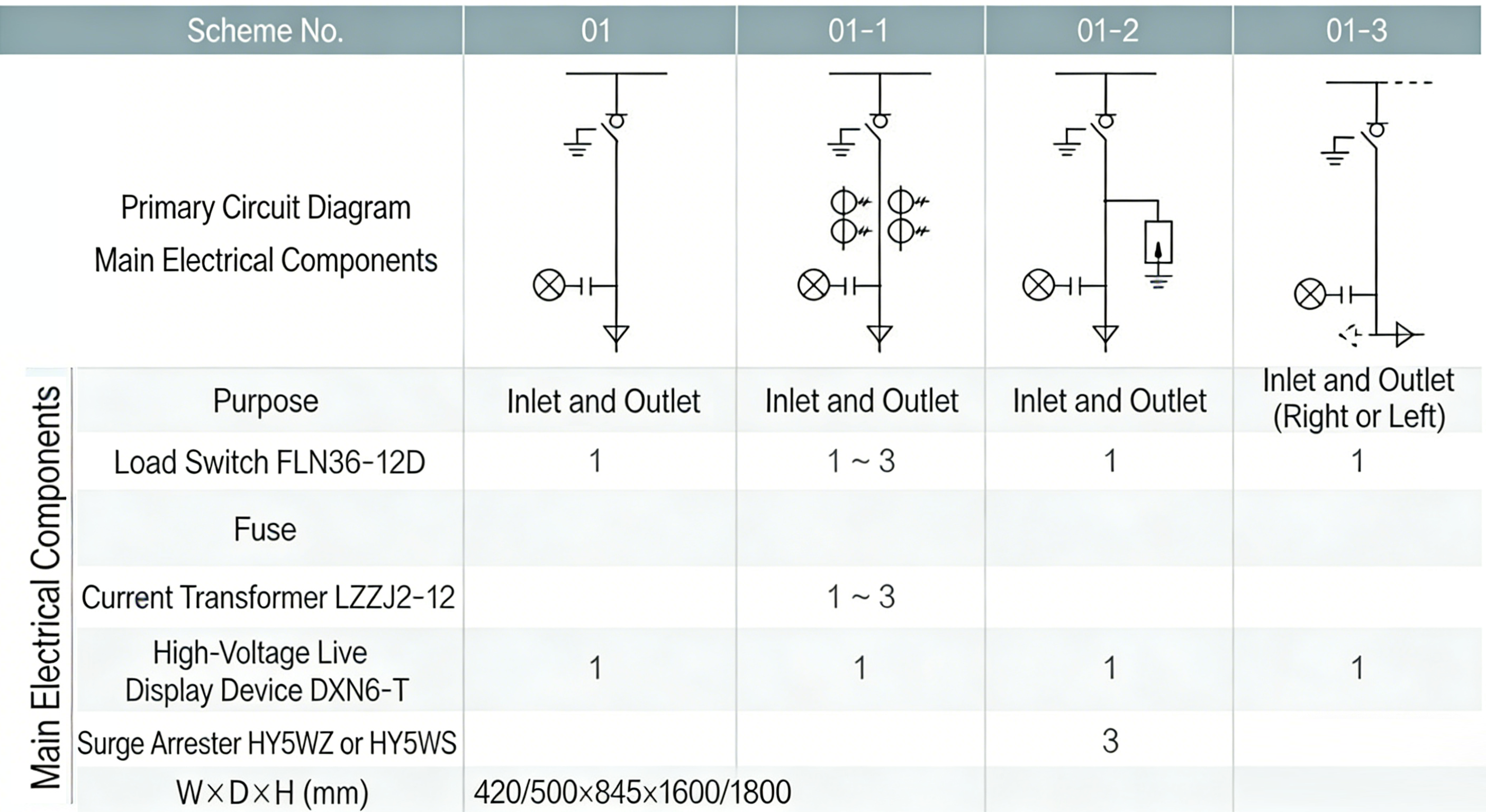
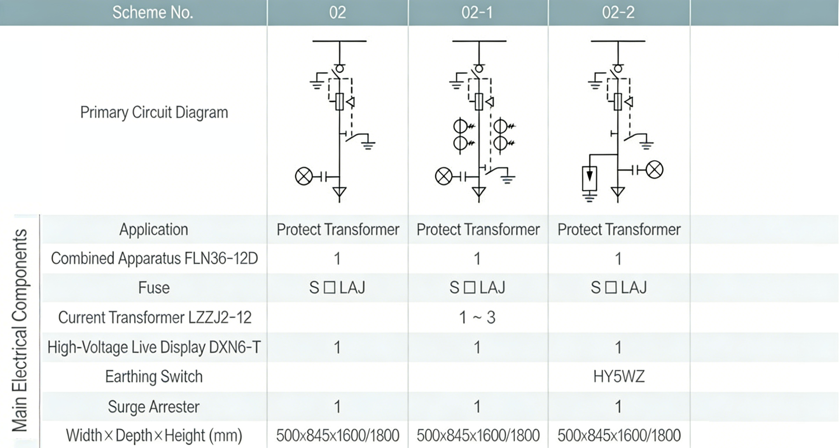
Serial No. Name Unit Value 1 Width of circuit breaker cabinet mm 750 2 Width of other cabinets mm 375,500 3 Height mm 1600,1850 4 Depth mm 980,900 5 Height of relay box mm 450 8. Technical Scheme Examples