 Yongce Group Co., Ltd.
Product Introduction
1. Product Brief Introduction
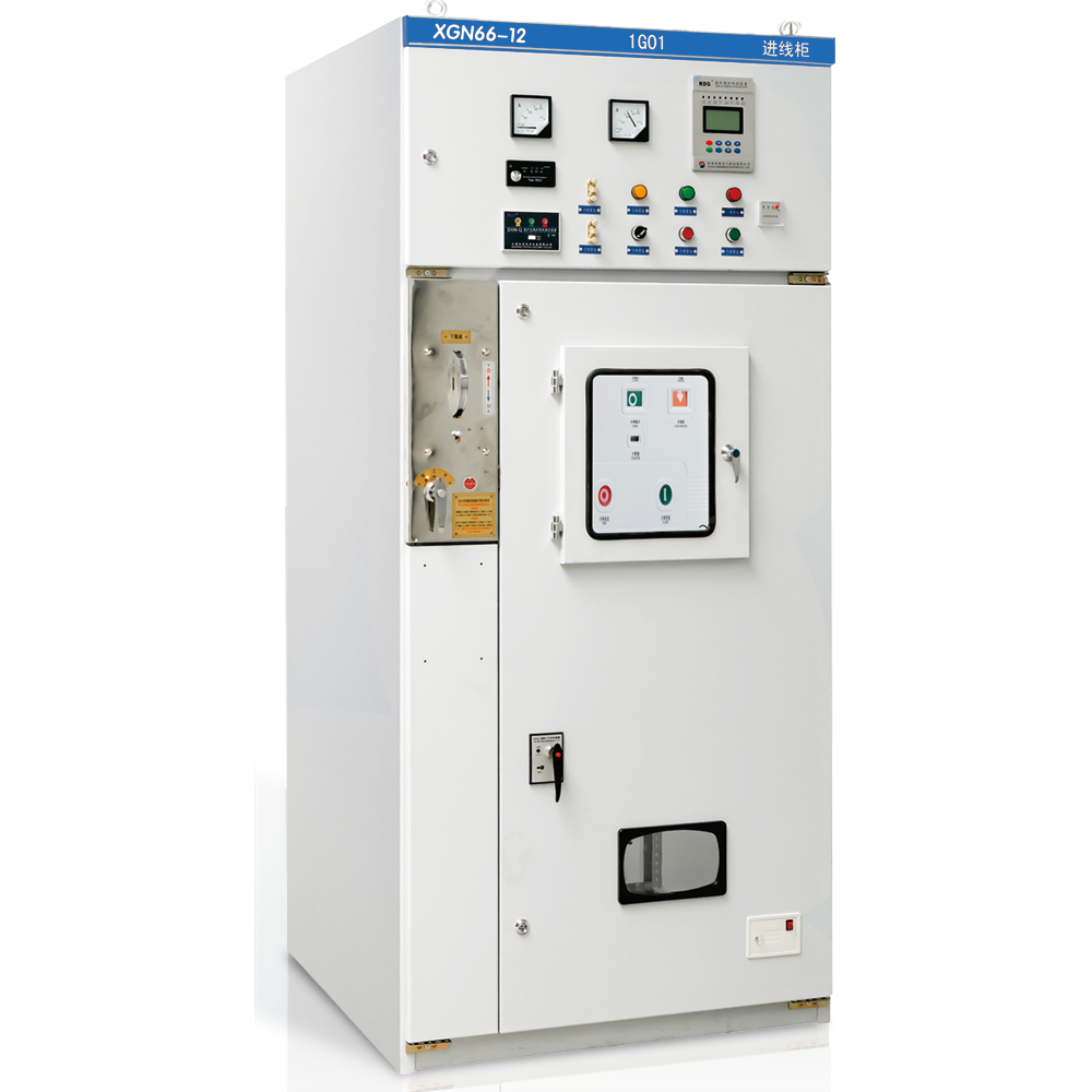
The XGN66-12 fixed enclosed switchgear (hereinafter referred to as switchgear) is a new generation of high-voltage electrical switchgear products of our company. It complies with the requirements of GB3906《3-35kV AC metal-enclosed switchgear》and DL/T404《Technical conditions for AC high-voltage switchgear assembies》, and also meets the international standard IEC60298《AC metal-enclosed switchgear and controlgear for rated voltages above 1kV up to and including 52kV》.
This product absorbs advanced domestic and foreign technologies, with small volume (only 50% of the volume of ordinary switchgear), reliable internal components, excellent performance, and reliable "five-prevention" interlocking mechanism. It is suitable for power system control, protection and monitoring of 3.6, 7.2, 12kV three-phase AC 50Hz single-busbar sectional indoor power distribution devices. It can be used in various types of power plants, substations, industrial and mining enterprises, high-rise buildings and other places, and can also be used in switch stations in combination with ring network cabinets.
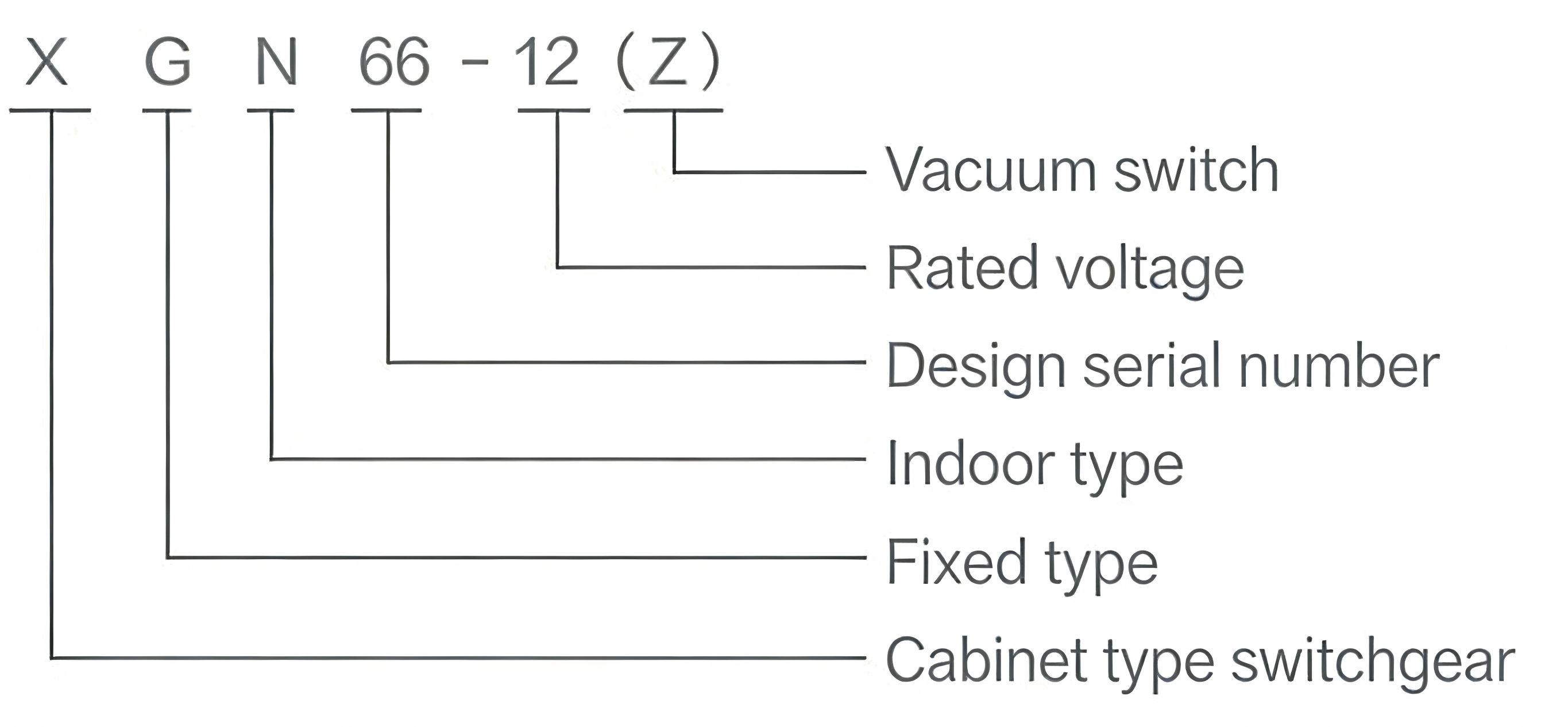
2. Model Meaning & Explanation
The coding of the product model contains the core structural characteristics and parameter information of the switchgear. The specific meaning of each part of the model is as follows:
3. Normal Operating Conditions
- Installation altitude shall not exceed 1000m;
- Ambient temperature: -25℃ ~ 40℃, the average temperature within 24 hours shall not exceed +35℃;
- Horizontal inclination shall not exceed 3 degrees;
- Earthquake intensity shall not exceed 8 degrees;
- No places with severe vibration, impact and explosion danger.
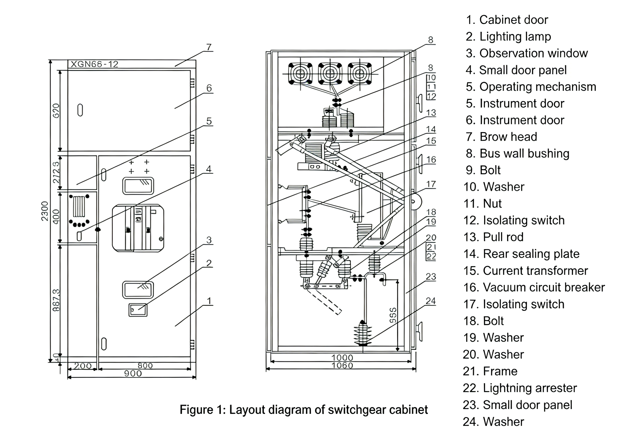
4. Structural Characteristics
- The cabinet body is welded with high-quality steel plates;
- The circuit breaker room is located at the lower part (rear part) of the cabinet body, which is convenient for installation, commissioning and maintenance. It is equipped with standard VS1 circuit breaker and has no pressure release channel to ensure personal safety;
- The integral withdrawable type metal enclosed switchgear can carry out safe and reliable maintenance of live incoming line in the main busbar;
- Integral protection grade IP2X;
- Equipped with reliable and fully functional mandatory mechanical interlocking device to effectively meet the "five-prevention" requirements;
- With reliable grounding system;
- The door is equipped with an observation window to clearly observe the working status of internal components;
- The operating mechanism adopts the same JSXGN interlocking mechanism as XGN2-12, which is simple, reliable and easy to use;
- The incoming and outgoing cables are connected at the front part of the cabinet body, which is convenient for user connection.
5. Main Technical Parameters and Component Models of Switchgear
| Serial No. | Item | Unit | Technical Parameters (3.6, 7.2, 12kV) |
|---|---|---|---|
| 1 | Rated Voltage | kV | 3.6, 7.2, 12 |
| 2 | Rated Power-Frequency Withstand Voltage | kV | Phase to phase: 42; Phase to ground: 48 |
| 3 | Rated Lightning Impulse Withstand Voltage | kV | Phase to phase: 75; Phase to ground: 85 |
| 4 | Rated Frequency | Hz | 50 |
| 5 | Rated Current | A | 630, 1250 |
| 6 | Rated Short-Circuit Breaking Current (RMS) | kA | 20, 25, 31.5 |
| 7 | Rated Short-Circuit Making Current (Peak) | kA | 50, 63, 80 |
| 8 | Rated Short-Time Withstand Current (Peak) | kA | 50, 63, 80 |
| 9 | Rated Rated Duration Short-Circuit Current (RMS) | kA | 20, 25, 31.5 |
| 10 | Protection Grade | - | IPX |
| 11 | Overall Dimension (Width × Depth × Height) | mm | 900 × 1000 × 2300 |
| 12 | Weight | kg | ≈600 |
6. Main Technical Parameters of QCE1-12 Vacuum Circuit Breaker
| Serial No. | Item | Unit | Technical Parameters (12kV) |
|---|---|---|---|
| 1 | Rated Voltage | kV | 12 |
| 2 | Rated Current | A | 630, 1250 |
| 3 | Rated Short-Circuit Breaking Current | kA | 20, 25, 31.5 |
| 4 | Rated Short-Circuit Making Current | kA | 50, 63, 80 |
| 5 | Rated Short-Time Withstand Current (4s, RMS) | kA | 20, 25, 31.5 |
| 6 | Rated Peak Withstand Current (Peak) | kA | 50, 63, 80 |
| 7 | Mechanical Life | times | 10000 |
| 8 | Rated Short-Circuit Breaking Current Switching Times | times | 50 |
| 9 | Rated Operating Sequence | - | Open-0.3s-Close-180s-Close |
| 10 | Contact Opening Distance | mm | 11±1 |
| 11 | Contact Overtravel | mm | 4±0.5 |
| 12 | Phase-to-Phase Center Distance | mm | 210 |
| 13 | Opening Speed | m/s | 1.2±0.2 |
| 14 | Closing Speed | m/s | 0.6±0.2 |
| 15 | Opening Time | ms | ≤60 |
| 16 | Closing Time | ms | ≤75 |
| 17 | Three-Phase Closing Simultaneity | ms | ≤2 |
| 18 | Closing Bounce | ms | ≤2 |
| 19 | Loop Resistance | μΩ | ≤45 |
| 20 | Accumulated Electrical Wear Thickness of Contacts | mm | 3 |
★ The technical parameters of other electrical components refer to their respective operation manuals.
★ For schemes with switch rated current greater than 1600A, please consult our company for solution.
7. Installation Requirements
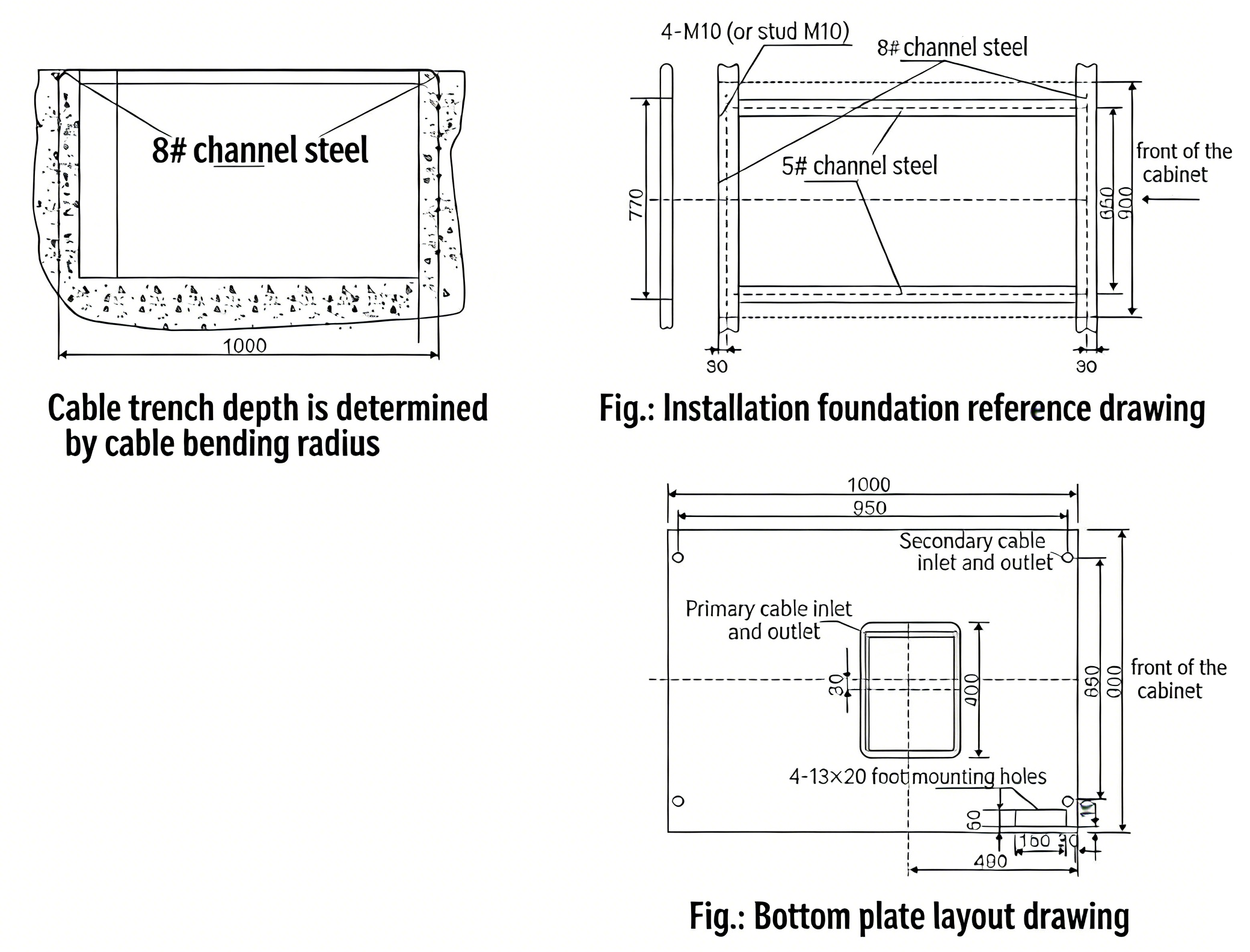
- For the installation foundation, refer to the following figure. The foundation anchor bolt shall be 1-3mm above the ground, the unevenness within each meter shall not exceed 1.5mm, and the unevenness within the full length shall not exceed 5mm;
- Place the switchgear on the foundation in sequence, adjust the installation position, then fix it with M12 bolts or spot welding, and tighten the phase-to-phase M8 bolts;
- After opening the rear cover to install the main busbar and the primary circuit, the contact surface of the terminal shall be cleaned, coated with neutral vaseline, and the primary cable shall be well sealed after installation;
- Connect the phase-to-phase grounding busbar, connect the switch cabinet into a whole according to the phase sequence, check whether the working grounding and protective grounding are reliable, check whether the grounding circuit is continuous and unobstructed, the working grounding resistance shall not be greater than 1000μΩ, and the protective grounding resistance shall not be greater than 4Ω;
- Install the secondary cable, which is introduced from the front lower part of the cabinet, enters the low-voltage chamber sideways, and is connected to the terminal block; or introduce it into the low-voltage chamber from the secondary small busbar of the cabinet top, and seal the cable hole after installation;
-
Clean up dust and sundries inside the cabinet.
8. Commissioning and Operation Requirements
- Conduct the following inspections and commissioning before commissioning: Check whether the model and specification of electrical components in the cabinet are consistent with the requirements; check whether the fasteners are loose; check whether the primary and secondary wiring is correct; operate the isolating switch, earthing switch and circuit breaker for 3-5 mechanical cycles, which shall be flexible without jamming, and check the "five-prevention" function; then add lubricating grease to the mechanical moving parts;
- Check the insulation level and circuit resistance of the switchgear and the mechanical characteristics of the circuit breaker according to the third clause of this manual and the factory test report. The test results shall be basically consistent with the factory test report.
9. Maintenance and Overhaul
- Users shall regularly maintain and overhaul the switchgear, including: Cleaning dust on the surface of insulators in each part regularly;
- Check the lubrication of each moving part, especially the insulation parts, to keep them flexible and reliable;
- Overhaul the circuit breaker, isolating switch, earthing switch and other components in accordance with their operation manuals;
- Check whether the electrical contact parts are in good condition, whether there is overheating phenomenon, and whether the circuit is unobstructed;
- Regularly check whether the fasteners are loose;
-
Carry out fault overhaul with the assistance of the manufacturer. For minor adjustments and small faults, users can carry out self-inspection and overhaul with reference to this manual and the respective manuals of main components.


")

")