 Yongce Group Co., Ltd.
Complete Product Introduction
1. Product Brief Introduction
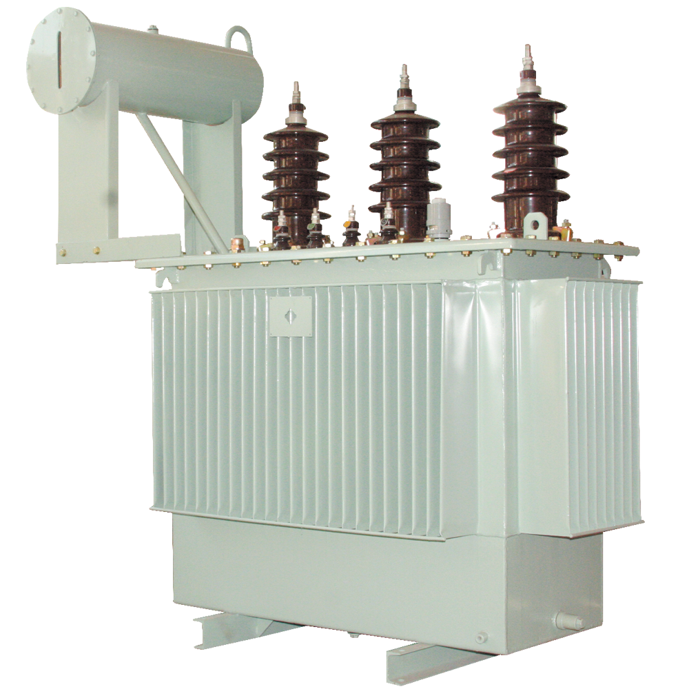
The SZ11-800~31500/35 oil-immersed transformer is suitable for 50Hz AC power systems with a rated operating voltage of 35kV, and is used as power transformation equipment for small and medium-sized substations.
2. Model Meaning & Explanation
The coding of the product model contains the core structural characteristics and parameter information of the transformer. The specific meaning of each part of the model is as follows:

- S: Three-phase
- Z: On-load tap changing
- 11: Design serial number
- □: Rated capacity (kVA)
- 35: High-voltage side voltage level (kV)
3. Executive Standards & Specifications
The design, production and inspection of the product are strictly in accordance with the following national and international standards to ensure product quality and performance compliance:
- GB1094.1-2013 Power Transformers - Part 1: General
- GB1094.3-2003 Power Transformers - Part 3: Insulation Levels, Dielectric Tests and External Clearances in Air
- GB/T1094.4-2005 Power Transformers - Part 4: Guide to Lightning Impulse and Switching Impulse Testing
- GB1094.5-2008 Power Transformers - Part 5: Ability to Withstand Short Circuit
- GB/T6451-2008 Technical Parameters and Requirements for Three-Phase Oil-Immersed Power Transformers
- International Standard IEC76 Power Transformers
4. Operating Conditions
- Installation altitude: Not exceeding 1000m
- Ambient temperature: -40°C ~ +40°C
5. Structural Characteristics
- Iron Core: Made of high-permeability grain-oriented cold-rolled silicon steel sheets. It is a core-type, fully oblique-seam stepped core with multi-stage stepped circular cross-section for core columns, and the yoke and core have equal cross-sections.
- Windings: Both windings are concentric type. The high-voltage winding has taps corresponding to the required tapping voltage, which are led to the tap changer. The switch is installed on the tank cover, and the tapping voltage can only be changed after the power supply is cut off.
- Safety Protection Devices: Equipped with gas relay and pressure relief valve.
- Oil Protection Devices: Equipped with an oil conservator with an oil level gauge at one end; a breather with oil seal is installed on the conservator.
- Oil Temperature Measuring Devices: Equipped with a glass thermometer tube seat installed on the top of the tank, extending 120±10mm into the oil; transformers of 1000kVA and above are equipped with outdoor signal thermometers.
- Transformer Tank and Accessories: The tank is generally not supplied with a trolley, and the welding position of the tank bottom bracket complies with GB6451-1999; an oil sampling valve is installed on the lower wall of the tank, and a sufficiently large oil drain valve is installed at the bottom of the tank.
6. Main Technical Parameters
| Rated Capacity (kVA) | Voltage Combination (kV) | Connection Symbol | Loss (kW) - S9 Type | No-load Current (%) | Short-Circuit Impedance (%) | |||
|---|---|---|---|---|---|---|---|---|
| High Voltage | High Voltage Tap Range | Low Voltage | Load Loss | No-Load Loss | ||||
| 800 | 38.5/35 | ±5% / ±2×2.5% | 3.15/6.3/10.5 | Yd11 | 9.90 | 1.23 | 1.00 | 6.5 |
| 1000 | 12.15 | 1.44 | 1.00 | 6.5 | ||||
| 1250 | 14.67 | 1.76 | 0.90 | 6.5 | ||||
| 1600 | 17.55 | 2.12 | 0.80 | 6.5 | ||||
| 2000 | 19.35 | 2.72 | 0.70 | 6.5 | ||||
| 2500 | 20.70 | 3.20 | 0.60 | 6.5 | ||||
| 3150 | 24.30 | 3.80 | 0.56 | 6.5 | ||||
| 4000 | 28.80 | 4.52 | 0.56 | 6.5 | ||||
| 5000 | Yd11 | 33.03 | 5.4 | 0.48 | 7 | |||
| 6300 | 36.90 | 6.56 | 0.48 | 7 | ||||
| 8000 | 40.50 | 9.00 | 0.42 | 7 | ||||
| 10000 | YNd11 | 47.70 | 10.88 | 0.42 | 7.5 | |||
| 12500 | 56.70 | 12.6 | 0.40 | 7.5 | ||||
| 16000 | 69.30 | 15.2 | 0.40 | 7.5 | ||||
| 20000 | 83.70 | 18.00 | 0.40 | 7.5 | ||||
| 25000 | YNd11 | 99.00 | 21.28 | 0.32 | 8 | |||
| 31500 | 118.80 | 25.28 | 0.32 | 8 | ||||
7. Overall Dimensions & Installation Dimensions

| Rated Capacity (kVA) | Product Dimensions (mm) | Footing (mm) | |||
|---|---|---|---|---|---|
| L | W | H | C1 | C2 | |
| 800 | 2630 | 1200 | 2150 | 820 | 820 |
| 1000 | 2750 | 1260 | 2200 | 820 | 820 |
| 1250 | 2870 | 1300 | 2300 | 820 | 820 |
| 1600 | 2890 | 1450 | 2450 | 820 | 820 |
| 2000 | 2930 | 1500 | 2540 | 1070 | 1070 |
| 2500 | 2970 | 2350 | 2750 | 1070 | 1070 |
| 3150 | 3090 | 2400 | 2850 | 1070 | 1070 |
| 4000 | 3170 | 2550 | 2940 | 1070 | 1070 |
| 5000 | 3180 | 2650 | 3100 | 1070 | 1070 |
| 6300 | 3350 | 2720 | 3150 | 1070 | 1070 |
| 8000 | 3560 | 2950 | 3160 | 1475 | 1475 |
| 10000 | 3600 | 3210 | 3210 | 1475 | 1475 |
| 12500 | 4050 | 3350 | 3480 | 1475 | 1475 |
| 16000 | 4160 | 3420 | 3580 | 1475 | 1475 |
| 20000 | 4480 | 3560 | 3760 | 1475 | 1475 |
| 25000 | 5250 | 3780 | 2980 | 1475 | 1475 |
| 31500 | 5690 | 4250 | 4050 | 1475 | 1475 |
8. Ordering Notes
When placing an order, the following information must be provided to ensure accurate product customization and delivery:
- Product model number
- Rated capacity
- High and low voltage rated voltage and high voltage tapping range
- Number of phases, frequency
- Connection group symbol
Note: Product size data is subject to adjustment, and the actual product size shall be based on the data reported by our company!
 Outdoor High-voltage Vacuum Circuit Breaker")
-12/0.4(F·R) Outdoor Prefabricated Substation (European Style)")


10-6-10kV Epoxy Resin Cast Dry-Type Transformer")
