 Yongce Group Co., Ltd.
Complete Product Introduction
1. Product Brief Introduction
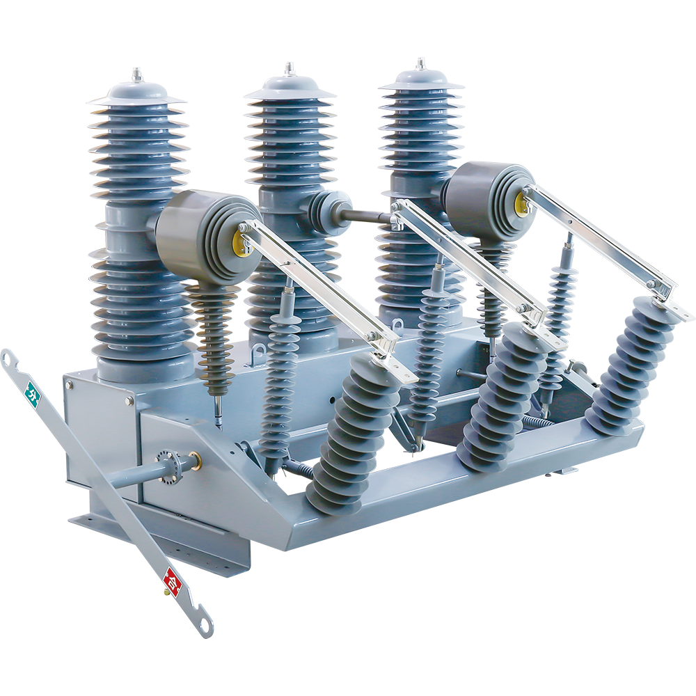
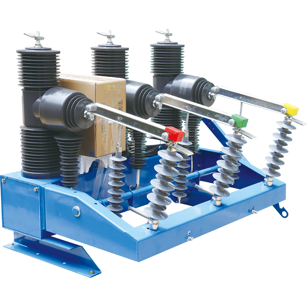
The ZW32-40.5 type outdoor high-voltage vacuum circuit breaker adopts a specially designed integrated solid-sealed pole and a highly reliable operating mechanism. This device is mainly used in medium-voltage overhead power lines for switching on and off load current, overload current, and short-circuit current.
2. Main Features
- Extremely high reliability
- Maintenance-free throughout the entire service life
- Long mechanical life and electrical life
- Integral design, small size, light weight, easy to install
3. Normal Operating Environment
- Ambient air temperature: -30℃ ~ +60℃;
- Altitude: not exceeding 3000m;
- Wind speed: not exceeding 34m/s;
- Vibration or shock from outside the switchgear and control equipment is negligible;
- Pollution grade: Grade IV;
- Storage temperature: -40℃ ~ +85℃.
4. Working Principle
4.1 Vacuum Principle
The ZW32-40.5 type outdoor high-voltage vacuum circuit breaker adopts a vacuum interrupter with high vacuum degree, using vacuum as the arc-extinguishing and insulating medium. When the moving and static contacts separate under the action of the operating mechanism to break the current, a vacuum arc will be generated in the contact gap. At the same time, due to the special structure of the contacts, a suitable longitudinal magnetic field will be generated in the contact gap, which keeps the vacuum arc in a diffused type and makes the arc current evenly distributed on the contact surface, maintaining a low arc voltage. When the arc current passes through zero, the residual ions, electrons and metal vapor will recombine or condense on the contact surface and shield cover within microseconds, and the insulation strength of the vacuum gap recovers quickly, thus extinguishing the arc and achieving the purpose of breaking. Due to the adoption of axial magnetic field type vacuum arc extinguishing, the vacuum circuit breaker has strong and stable breaking capacity.
4.2 Electric Energy Storage
The motor outputs torque to the small gear of the mechanism, which is transmitted to the large gear on the main shaft, thereby driving the crank arm to rotate and storing energy for the closing spring. When the screw on the crank arm presses down the travel switch, the motor circuit is cut off and the spring energy storage is completed.
4.3 Manual Energy Storage
The operating mechanism outputs the shaft, and the small gear on the output shaft transmits the torque to the large gear fully meshed with the small gear, thereby driving the crank arm to rotate and storing energy for the closing spring.
4.4 Closing Electromagnetic Operation
After the mechanism receives the closing command, the armature of the closing electromagnet moves upward, pushing the closing release lever to move upward, making the closing half-shaft rotate counterclockwise. The constraint on the closing pawl is released, and at the same time, the closing pawl rotates counterclockwise under the pressure of the roller, releasing the energy storage maintaining mechanism. The cam on the main shaft generates an impact force due to the contraction of the closing spring, hitting the energy storage maintaining latch (the latch on the output shaft), and completing the closing operation through the connecting rod to drive the switch on.
4.5 Manual Closing Operation
When the crank installed on the closing half-shaft rotates counterclockwise, it drives the closing half-shaft to rotate counterclockwise, producing the same effect as the closing electromagnetic operation.
4.6 Reclosing Operation
After the mechanism releases the energy of the closing spring to complete the closing operation, in the closing state, the mechanism performs energy storage again. After completing the energy storage operation, the mechanism is in the state of energy storage for closing. In this state, once the correct command is received, the mechanism can realize one automatic reclosing operation.
4.7 Opening Electromagnetic Operation
After the mechanism receives the opening command, the armature of the opening electromagnet moves upward, pushing the opening release lever to move upward, making the opening half-shaft rotate counterclockwise. The constraint on the opening pawl is released, and at the same time, the opening pawl rotates counterclockwise under the pressure of the roller, and the crank arm rotates counterclockwise under the thrust of the opening spring inside the switchgear, thus completing the opening operation.
4.8 Manual Opening Operation
When the crank installed on the opening half-shaft rotates counterclockwise, it drives the opening half-shaft to rotate counterclockwise, producing the same effect as the opening electromagnetic operation.
4.9 Overcurrent Trip Operation
When the overcurrent coil passes through the specified tripping current, the electromagnet acts and the push rod pushes the trip lever to rotate the opening half-shaft counterclockwise, releasing the constraint on the opening pawl, thus producing the same effect as the opening electromagnetic operation and completing the overcurrent trip operation of the circuit breaker.
5. Main Technical Parameters
| Serial No. | Item | Unit | Data |
|---|---|---|---|
| 01 | Rated Voltage | kV | 40.5 |
| 02 | Rated Current | A | 630/1250 |
| 03 | Rated Frequency | Hz | 50 or 60 |
| 04 | Withstand Voltage for 1min at Power Frequency (Wet/Dry) Phase to Phase, Phase to Ground/Break | kV | 80/95/95 |
| 05 | Lightning Impulse Withstand Voltage (Peak) Phase to Phase, Phase to Ground/Break | kV | 185 |
| 06 | Rated Breaking Current | kA | 25/31.5 |
| 07 | Rated Making Current (Peak) | kA | 63/80 |
| 08 | Rated Withstand Current | kA | 25/31.5 |
| 09 | Withstand Current for 4s | kA | 63/80 |
| 10 | Rated Operating Sequence | - | Open-0.1s-Close-Open-3min-Close-Open-60s Recovery |
| 11 | Rated Number of Breaking Operations | times | 30 |
| 12 | Mechanical Life | times | 10000 |
| 13 | Mechanism Control Voltage | V | AC/DC220 |
| 14 | Secondary Circuit Withstand Voltage for 1min at Power Frequency | kV | 2 |
| 15 | Contact Opening Distance | mm | 16±1 |
| 16 | Contact Over Travel | mm | 4±0.5 |
| 17 | Opening Speed | m/s | 1.4-1.8 |
| 18 | Closing Speed | m/s | 0.4-0.8 |
| 19 | Contact Closing Bounce Time | ms | ≤5 |
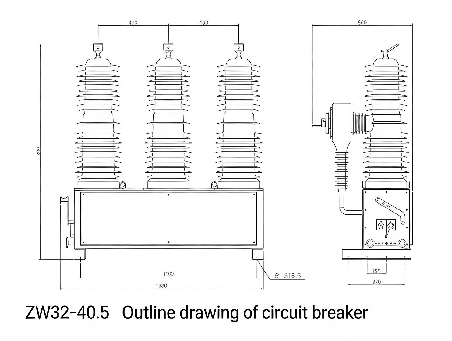
| 20 | Center Distance Between Three Phases | mm | 460±2 |
| 21 | Three-Phase Closing/Opening Asynchronism | ms | ≤2 |
| 22 | Equivalent Circuit Resistance of Each Phase | μΩ | <80 |
| 23 | Closing Time | ms | ≤100 |
| 24 | Opening Time | ms | ≤50 |
| 25 | Weight | Kg | 270 |
6. Structure and Working Principle
The ZW32-40.5 type outdoor high-voltage vacuum circuit breaker is mainly composed of an integrated solid-sealed pole, a current transformer, an operating mechanism and a box body. This type of circuit breaker is designed for miniaturization, and the outer shell adopts high-quality stainless steel. The current transformer can be selected according to user needs.
The ZW32-40.5 type outdoor high-voltage vacuum circuit breaker is equipped with a matching intelligent control unit, which can realize on-site switch closing and opening operations, and can also be remotely operated through a communication interface. Other information of the circuit breaker can also be transmitted to the control center, and the communication channel can select cable, optical fiber, GPRS/CDMA, GSM, etc.
7. Ordering Notes
When placing an order for the ZW32-40.5 type outdoor high-voltage vacuum circuit breaker, please provide the following information to ensure that the product meets the actual use requirements:
- Exact product model and specification
- Required rated current (A)
- Operating environmental conditions (if special requirements)
- Special technical requirements (if any, such as type of current transformer, communication mode, etc.)


