Yongce Group Co., Ltd.
Product Introduction
1. Product Brief Introduction
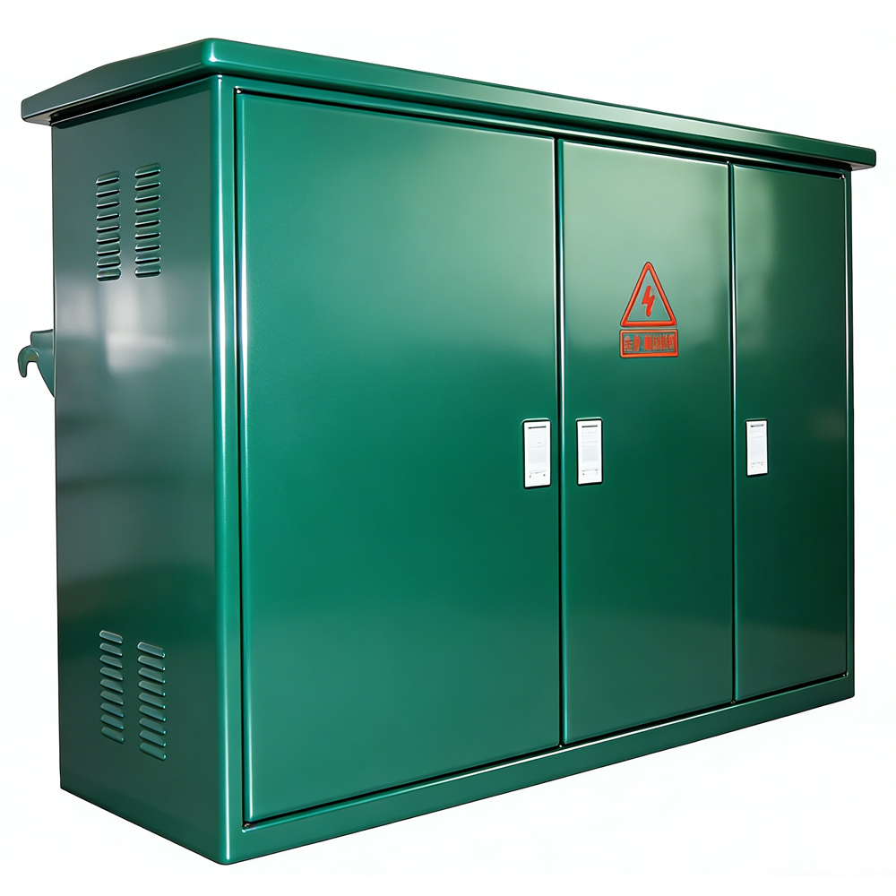
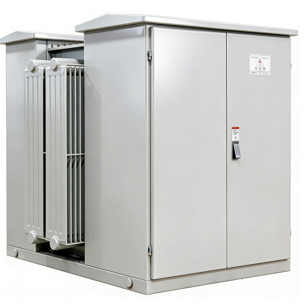
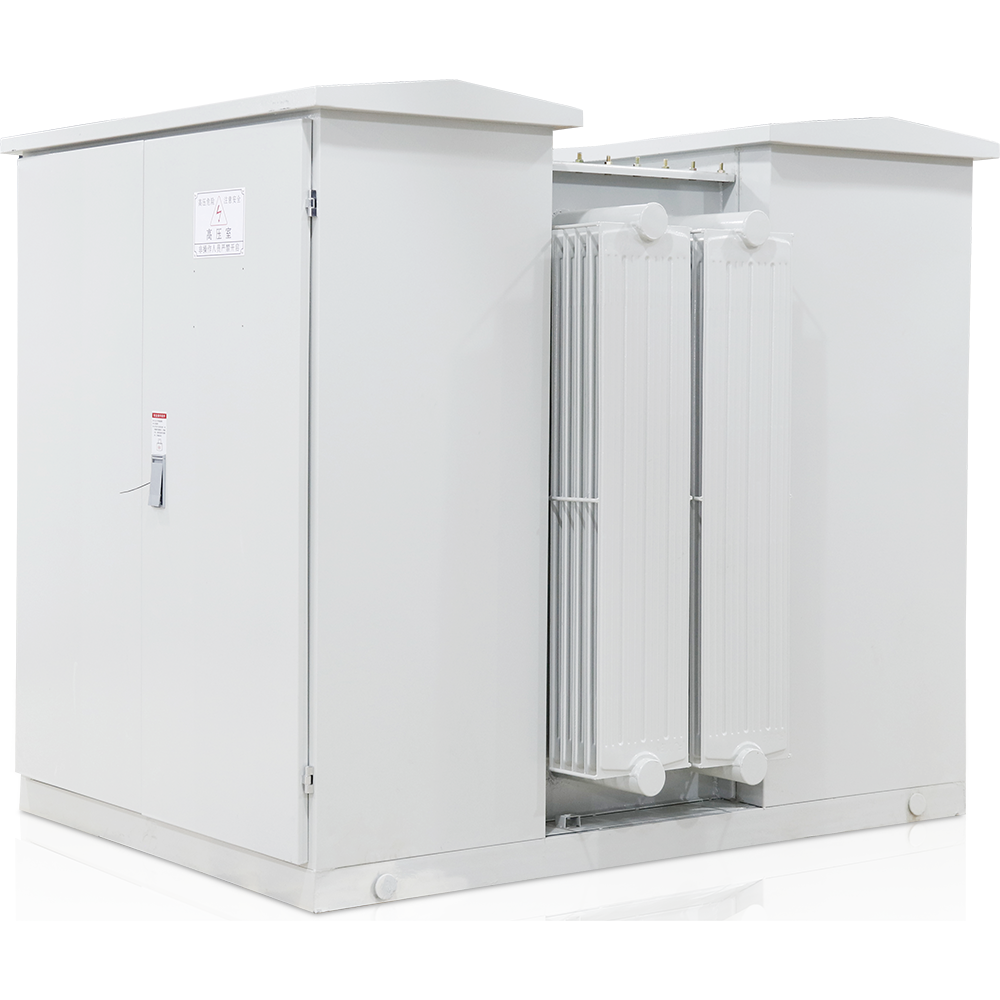
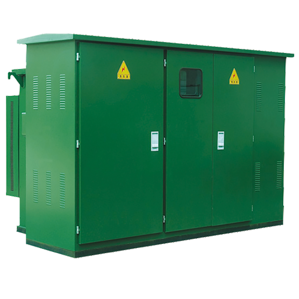
This product is developed by absorbing foreign professional technologies and combining with the actual domestic situation. The whole set of products has the characteristics of small volume, convenient installation and maintenance, low noise, low loss, anti-theft, strong overload capacity, full sealing, etc. It is suitable for new districts, green belts, parks, stations, hotels, construction sites, airports and other places.
The YB27-12 series prefabricated box-type substation is suitable for 10kV ring network power supply, dual power supply or terminal power supply system, and is used as power transformation, metering, compensation control and protection device.
This product complies with the following standards: GB/T17467-1998 "High and Low Voltage Prefabricated Substations", DL/T537-93 "Ordering Technical Conditions for 6(35)kV Box-type Substations".
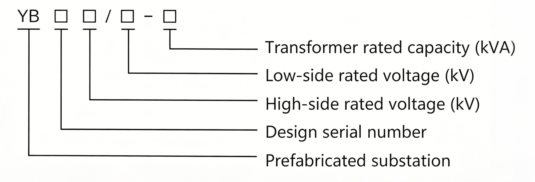
2. Model Meaning & Explanation
The coding of the product model contains the core parameter information of the prefabricated substation. The specific meaning of each part of the model is as follows:
3. Operating Conditions
- Altitude shall not exceed 1000m;
- Ambient temperature: -35℃ ~ 40℃;
- Relative humidity: daily average value not more than 95%, monthly average value not more than 90%;
- Installation site: places without fire, explosion hazard, chemical corrosive gas and with good ventilation, and the ground inclination is not more than 3°.
4. Product Characteristics
- Fully insulated, fully sealed, less maintenance, can reliably ensure personal safety;
- Compact structure, volume is 1/3-1/5 of the same capacity European style, low height;
- Can adopt split structure to avoid oil pollution caused by oil leakage from the transformer oil tank;
- High-voltage side adopts double fuse full-range protection, greatly reducing costs;
- Can be used for ring network or terminal, and the cable head can be plugged and unplugged in emergency when the load current is 200A;
- The box body adopts honeycomb double-layer composite board, with heat insulation and heat dissipation functions;
- Low-voltage side is equipped with electronic ball protection device, which can quickly disconnect the main incoming switch when abnormal voltage occurs in the system;
- High-voltage oil-immersed load switch or SF6 load switch can be upgraded electrically, laying a foundation for realizing distribution automation;
- Adopt oil-immersed S9 or more excellent S11 series transformers.
5. Main Technical Parameters
5.1 Technical Parameter Table of Prefabricated Substation
| Serial No. | Name | Unit | Technical Parameters |
|---|---|---|---|
| 1 | Rated Voltage | kV | 10/0.4 (High/Low Voltage) |
| 2 | Maximum Voltage | kV | 12 (High Voltage Side) |
| 3 | Rated Frequency | Hz | 50 |
| 4 | Rated Capacity | kVA | 50-1600 |
| 5 | 1-minute Power Frequency Withstand Voltage | kV | 35 |
| 6 | Lightning Impulse Voltage | kV | 75 |
| 7 | Cooling Method | - | Oil-immersed Self-cooling |
| 8 | High Voltage Rear Fuse Breaking Current | kA | 50 |
| 9 | Plug-in Fuse Breaking Current | kA | 2.5 |
| 10 | Ambient Temperature | ℃ | -35~40 |
| 11 | Allowable Temperature Rise of Coil | K | 65 |
| 12 | No-load Voltage Regulation | - | ±5% or ±2×2.5% |
| 13 | Noise Level | dB | 50 |
| 14 | Protection Grade | - | IP43 |
5.2 Technical Parameter Table of Transformer
A new-type core of the S9 series transformer is adopted, which features low loss, excellent overload capacity and high short-circuit resistance. All fasteners are anti-loosening treated to achieve core-lifting free maintenance. The higher-performance S10 and S11 series transformers are also available as an option.
| Capacity (kVA) | Voltage (kV) | Connection Group | No-load Current (%) | No-load Loss (kW) | Impedance Voltage (%) | Load Loss (kW) | |||||||
|---|---|---|---|---|---|---|---|---|---|---|---|---|---|
| High Voltage | Low Voltage | S9 | S10 | S11 | S9 | S10 | S11 | S9 | S10 | S11 | |||
| 50 | 10±5% or ±2×2.5% | 0.4 | Dyn11 or Yyn0 | 2.0 | 1.9 | 0.75 | 0.17 | 0.15 | 0.12 |
|
0.87 | 0.83 | 0.87 |
| 63 | 1.9 | 1.8 | 0.7 | 0.2 | 0.18 | 0.14 |
|
1.04 | 0.99 | 1.04 | |||
| 80 | 1.9 | 1.7 | 0.7 | 0.25 | 0.22 | 0.175 |
|
1.25 | 1.2 | 1.25 | |||
| 100 | 1.8 | 1.55 | 0.65 | 0.29 | 0.26 | 0.2 |
|
1.5 | 1.42 | 1.5 | |||
| 125 | 1.7 | 1.45 | 0.65 | 0.34 | 0.3 | 0.235 | 4.0 | 1.8 | 1.72 | 1.8 | |||
| 160 | 1.6 | 1.3 | 0.6 | 0.4 | 0.36 | 0.27 |
|
2.2 | 2.12 | 2.2 | |||
| 200 | 1.5 | 1.2 | 0.55 | 0.48 | 0.43 | 0.33 |
|
2.6 | 2.5 | 2.6 | |||
| 250 | 1.4 | 1.1 | 0.5 | 0.56 | 0.5 | 0.39 |
|
3.05 | 2.9 | 3.05 | |||
| 315 | 1.4 | 1.0 | 0.45 | 0.67 | 0.59 | 0.465 |
|
3.65 | 3.45 | 3.65 | |||
| 400 | 1.3 | 1.0 | 0.4 | 0.8 | 0.71 | 0.56 |
|
4.3 | 4.15 | 4.3 | |||
| 500 | 1.2 | 1.0 | 0.4 | 0.96 | 0.85 | 0.67 |
|
5.15 | 4.82 | 5.15 | |||
| 630 | 1.1 | 0.8 | 0.4 | 1.2 | 1.06 | 0.81 |
|
6.2 | 5.86 | 6.2 | |||
| 800 | 1.0 | 0.7 | 0.35 | 1.4 | 1.23 | 0.98 |
|
7.5 | 7.2 | 7.5 | |||
| 1000 | 1.0 | 0.6 | 0.3 | 1.7 | 1.5 | 1.15 | 4.5 | 10.3 | 9.8 | 10.3 | |||
| 1250 | 0.9 | 0.6 | 0.27 | 1.95 | 1.72 | 1.36 |
|
12.0 | 12.2 | 12.0 | |||
5.3 Technical Parameter Table of Load Switch
The load switch is an oil-immersed type with a three-phase interlocked switch and a spring operating mechanism; it is capable of on-load switching on and off operations, and its opening and closing speed is independent of the operating force. Types including two-position, four-position T-type and four-position V-type are available for selection.
| No. | Name | Unit | Four-position Ring Network Load Switch | Two-position Load Switch |
|---|---|---|---|---|
| 1 | Rated Short-circuit Withstand Current | kA | 63.0 | 31.5 |
| 2 | Rated Short-time Withstand Current | kA | 31.5 | 31.5 |
| 3 | Rated Mechanical Endurance | times | 2000 | 200 |
| 4 | Number of Rated Closing Times | times | 2 | 2 |
| 6 | Lightning impulse withstand (phase to phase and phase to ground) | kV | 95 | 95 |
| 7 | Peak voltage full wave (isolated fracture) | kV | 75 | 75 |
| 8 | 1min power frequency withstand voltage (phase to phase and phase to ground) | kV | 42 | 42 |
| 9 | 1min power frequency withstand voltage (isolated fracture) | kA | 48 | 48 |
| 10 | Rated peak withstand current | kV | 31.5 | 31.5 |
5.4 Technical Parameter Table of Fuse (Recommended Selection and Configuration Table for the Company's Oil-Immersed Fuses)
The high-voltage side of the American-style pad-mounted transformer is provided with full-range protection by the series connection of a backup protection fuse and a plug-in fuse, featuring a simple principle, economy and reliability. The backup protection fuse is an oil-immersed high-voltage current-limiting fuse with a large breaking capacity, which only operates in the event of an internal transformer fault. The plug-in fuse is equipped with a dual-sensitive fuse link that provides dual protection against overcurrent and over-temperature. After the dual-sensitive fuse link blows, the fuse core can be conveniently replaced on site.
| No. | Three-phase Transformer Capacity (kVA) | Primary voltage of the transformer (10kV) | |
|---|---|---|---|
| XRNT1 Rated Current (A) | PRNT1 Overload Rated Current (A) | ||
| 1 | 30 | 10 | 6 |
| 2 | 50 | 16 | 8 |
| 3 | 80 | 20 | 10 |
| 4 | 100 | 25 | 15 |
| 5 | 125 | 31.5 | 25 |
| 6 | 160 | 40 | 25 |
| 7 | 200 | 50 | 40 |
| 8 | 250 | 63 | 40 |
| 9 | 315 | 80 | 50 |
| 10 | 400 | 63 | 50 |
| 11 | 500 | 100 | 60 |
| 12 | 630 | 125 | 65 |
| 13 | 800 | 160 | 65 |
| 14 | 1250 | 160 | 140 |
| 15 | 1600 | 200 | 140 |
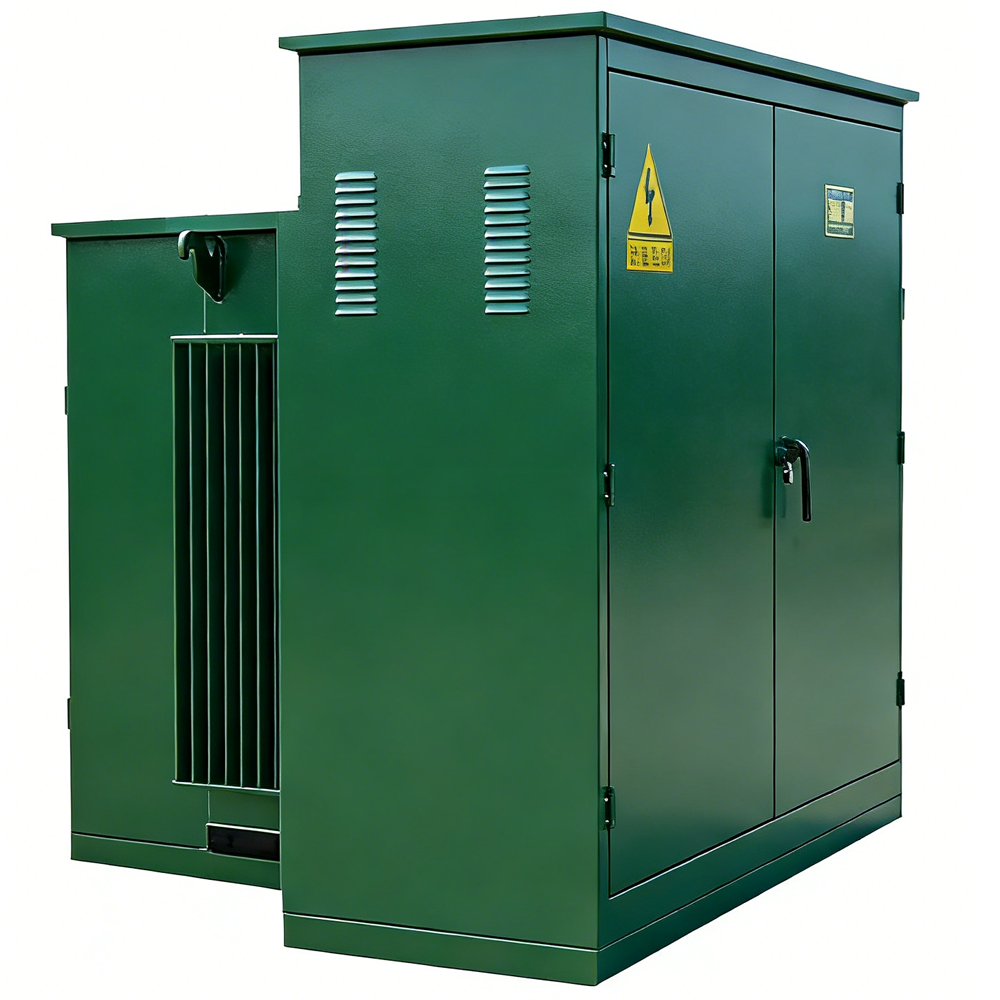
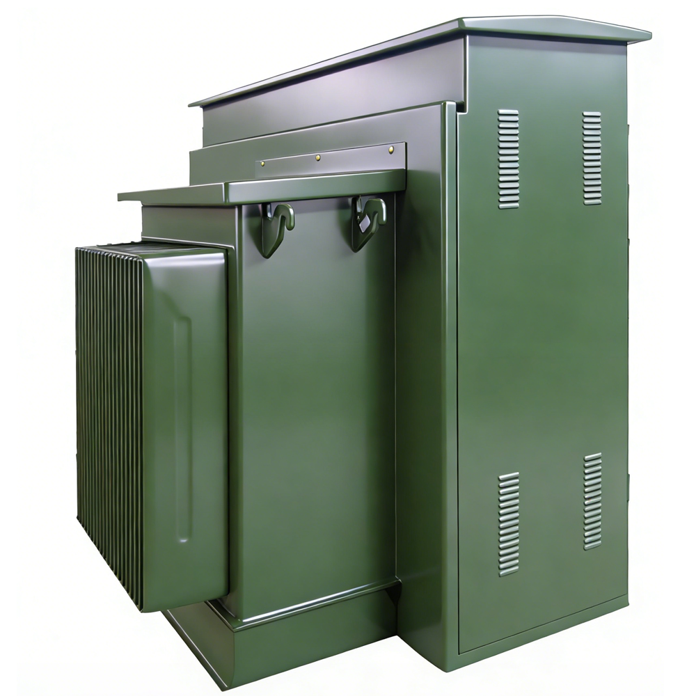
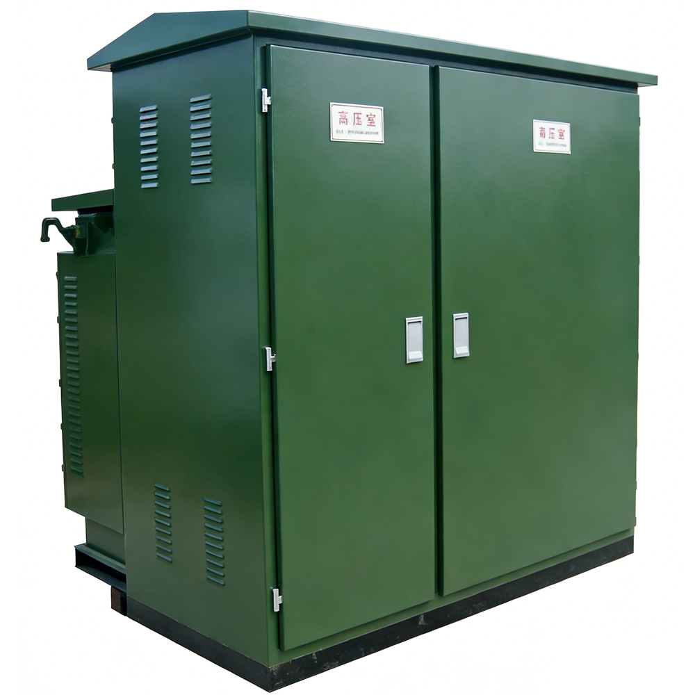
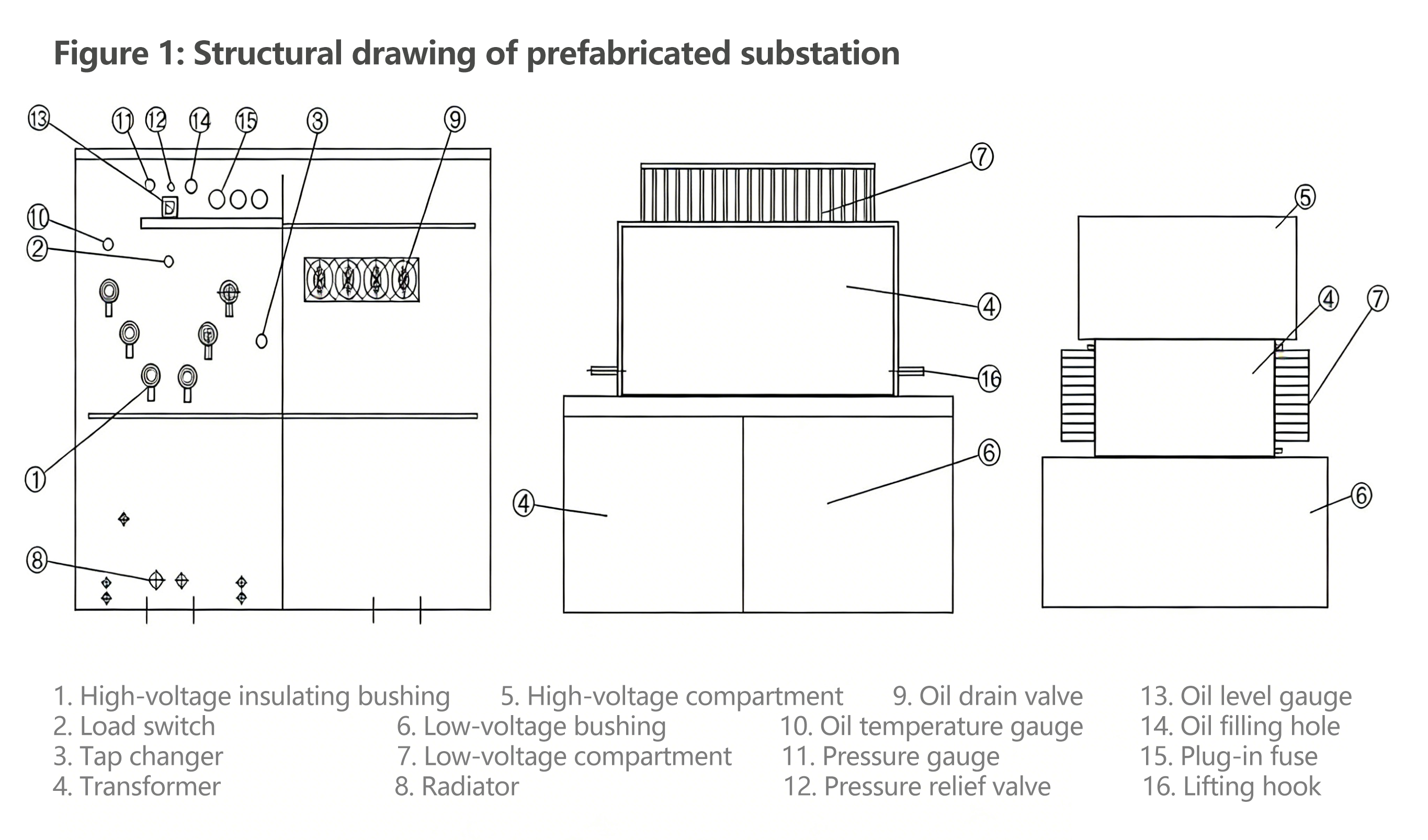
6. Substation Structure
The cabinet structure of this product consists of three parts: the high-voltage compartment, the low-voltage compartment and the oil tank compartment. The high-voltage compartment contains high-voltage cable accessories, load switches, off-circuit tap changers, plug-in fuses, pressure relief valves, oil level gauges, oil temperature gauges and oil drain valves. The low-voltage compartment is equipped with low-voltage bushings, low-voltage metering instruments, circuit breakers and capacitive compensation devices. The oil tank compartment houses transformer windings and iron cores as well as radiators; the high-voltage load switches and fuses are all installed inside the oil tank. According to project requirements, the structure of the pad-mounted transformer can be designed into a pin-shaped type or a mesh-shaped type, as shown in the figure below.
7. Operating Instructions
7.1 Operation of Load Switch
The oil-immersed load switches used in American-style pad-mounted transformers are available in three types—two-position, four-position T-type and four-position V-type—based on their functional differences, and one type can be selected as required.
Their respective operation methods are as follows:
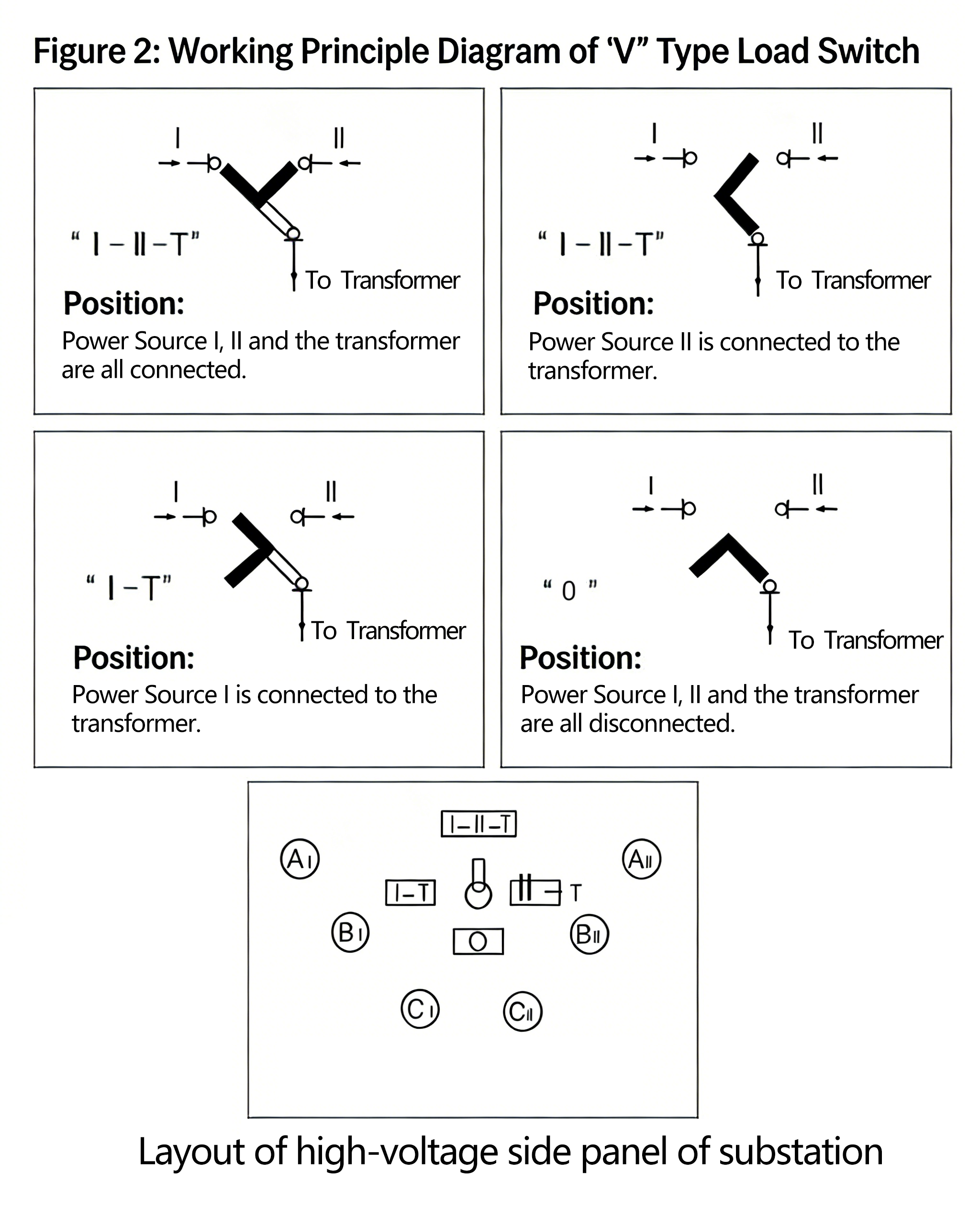
The four-position V-type load switch is shown in Figure 2. Its power plate adopts a V-shaped structure (the black part in the figure). In the figure, "I, II" represent the incoming and outgoing lines for ring network power supply, and "T" represents the high-voltage incoming line of the transformer connected via the backup fuse and plug-in fuse. The ring network load switch can switch the power network under load conditions.
Four Working Positions of the Load Switch:
- At the I-II-T position: Network I and Network II are connected, and the transformer is energized (the substation functions as a ring network).
- At the I-T position: Network I is connected to the transformer (the substation functions as a terminal).
- At the II-T position: Network II is connected to the transformer (the substation functions as a terminal).
- At the O position: Network I, Network II and the transformer are all disconnected (all de-energized).
Insert the special operating handle into the rotating shaft of the load switch and rotate it clockwise or counterclockwise by approximately 130 degrees. The power plate rotates one gear each time the load switch is operated. Example of switch operation: Switch the power supply from Network I to Network II.
Method 1:
- a. Insert the special operating handle into the switch shaft;
- b. Rotate the switch clockwise once, and the V-shaped blade of the switch is at the I-II-T position at this time;
- c. Rotate clockwise once more, and the V-shaped blade is between II-T to supply power from Network II at this time; the operation is completed.
Method 2:
- a. Insert the special operating handle into the switch shaft;
- b. Rotate the switch counterclockwise once, and the V-shaped blade of the switch is at the O position at this time;
- c. Rotate counterclockwise once more, and the V-shaped blade is between II-T to supply power from Network II at this time; the operation is completed.
Both methods above can realize the power supply switch from Network I to Network II, while Method 2 is safer and more reasonable. After Network I is cut off, it will not be re-energized; meanwhile, if a fault occurs in Network II, it will not cause closing on the faulty network. In contrast, Method 1 may lead to dual power supply. When switching the power supply from Network I to Network II, faults may occur due to reasons such as inconsistent power supply phases.
7.2 Four-Position Ring Network Load Switch (T-Type)
The working principle of the four-position T-type load switch is shown in Figure 3, and its operating method is the same as that of the V-type.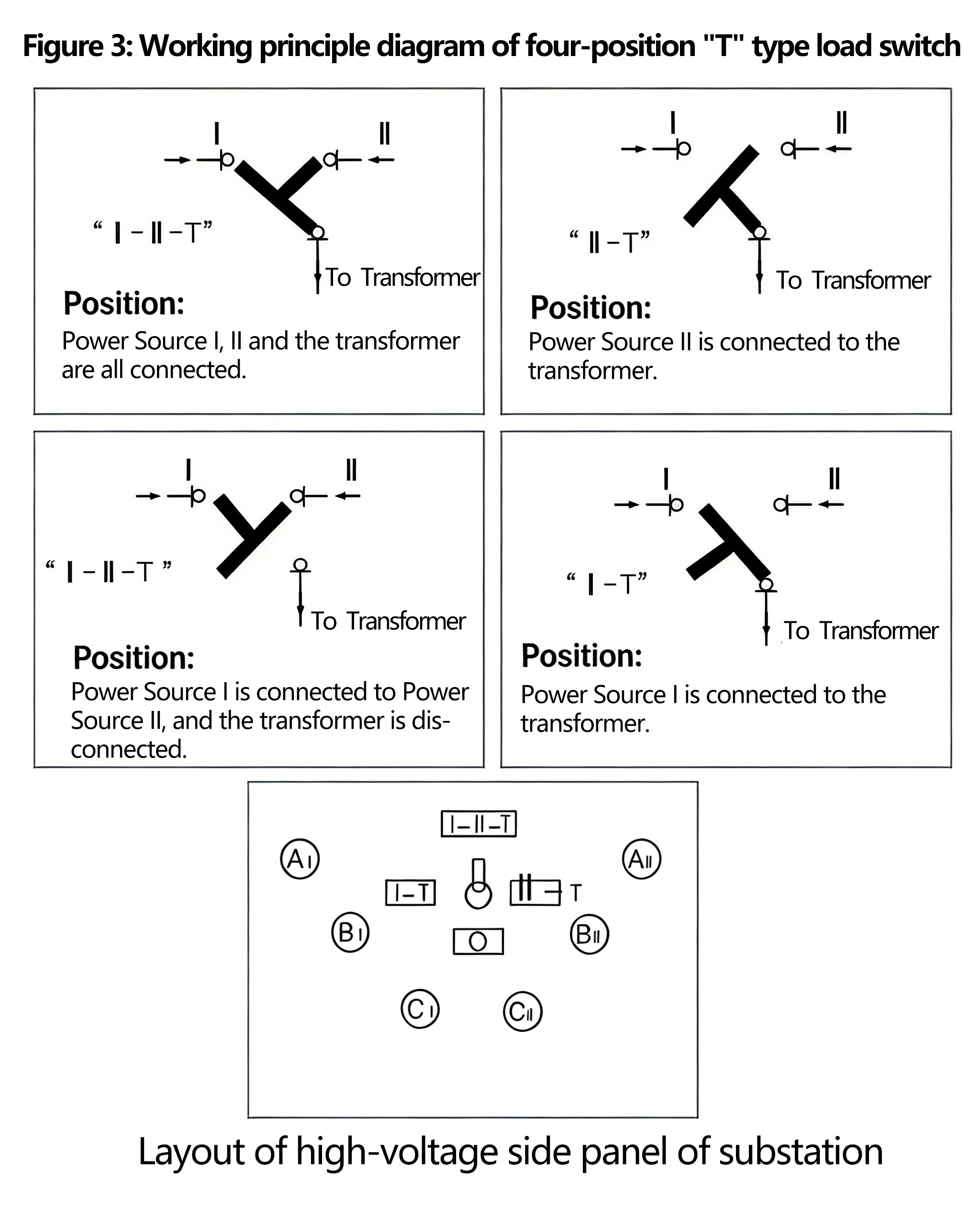
Two-Position Terminal Load Switch
Its structural drawing is shown in Figure 4, where 1 is connected to the high-voltage incoming line terminal. When operating, the user inserts the special operating handle into the rotating shaft of the load switch and rotates it counterclockwise by 90° to switch the load switch to the open position. The terminal load switch is only used to cut off the transformer branch in the terminal power supply mode or operate when replacing the fuse core of the plug-in fuse. Therefore, the terminal load switch has only two positions (open and close). Owing to its compact size, it features a small operating force and is easy to operate and use. To reduce oil contamination inside the oil tank, it is recommended that the user disconnect the low-voltage main switch or outgoing line switch to cut off the low-voltage side load before operating the load switch.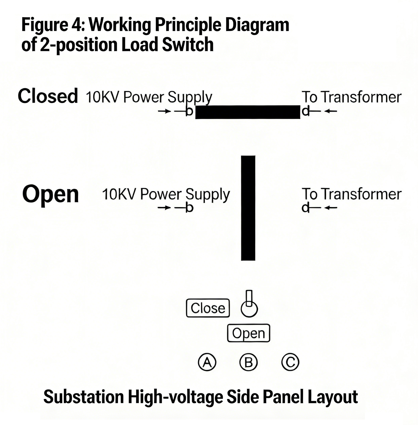
Cable Head
- a. The high-voltage incoming and outgoing lines of the 12kV prefabricated substation adopt cable connections. Epoxy-cast insulating bushings lead the high-voltage power supply out of the oil tank. For the convenience of factory testing and user acceptance testing, the insulating bushings themselves are capable of withstanding power-frequency withstand voltage and lightning impulse withstand voltage.
- b. Select an elbow-type or T-type cable head matching the cable cross-section. Clean its inner and outer surfaces and the surface of the insulating bushing with anhydrous ethanol, apply a small amount of 7501-type vacuum silicone grease on the bushing surface, and install it in accordance with the special installation specifications of the cable work area. For the installation of the cable head, refer to the attached instruction manual.
Replacement of Plug-In Fuse
The plug-in fuse is a component with an externally replaceable fuse core. For replacement:
- First, pull the button of the pressure relief valve on the upper oil tank to balance the pressure inside and outside the oil tank.
- To ensure the safety of operators and equipment, the plug-in fuse must be plugged and unplugged without load. Therefore, first cut off the power of the low-voltage switch to disconnect all low-voltage side loads.
- Then use the operating handle to switch the load switch to the position where the power supply and the transformer are disconnected.
- Next, use the operating handle to loosen the handle on the fuse holder, then rotate it by about 90° to eliminate the adhesion between the gasket and the outer wall.
- Pull out the fuse element of the fuse obliquely upward by 70-80mm and let it stand for a few seconds to allow the oil on the fuse element to drain off partially before pulling it out completely, so as to prevent oil from dripping on other components outside the oil tank.
- Wipe the surface of the fuse element clean with a dry cotton cloth before replacing the fuse core.
- Note: When replacing, pay close attention to the parameters marked on the fuse core—fuse cores with different parameters cannot be used interchangeably. The replacement steps are shown in the figure. After replacing the fuse core, insert the fuse element firmly into the fuse holder. When rotating the handle on the fuse element to the locked position, ensure that the gasket is tightly attached to the fuse holder and the handle is buckled on the boss, so as to ensure the substation is fully sealed and free from moisture ingress. Then close the high-voltage load switch and low-voltage switch again to restore power supply.
- As the substation is a three-phase system, for either the backup protection fuse or the plug-in fuse, if the fuse element of one phase is blown, the fuse elements of all three phases should generally be replaced, unless it is confirmed that only the fuse element of one phase has carried the fault current.
7.3 Replacement Steps of Plug-in Fuse
- Open the low-voltage main switch;
- Open the high-voltage load switch;
- Pull the ring of the pressure relief valve to release pressure;
- Hook the operation hole and rotate it upward by 90 degrees;
- Pull it upward by 100mm, pause for a moment, then pull it out completely;
- Wipe it dry with a clean cotton cloth;
- Replace the fuse core as shown in the figure below;
-
Quickly insert the replaced fuse core into the original hole and fasten it in place.
8. Transportation, Installation and Maintenance
8.1 Transportation
The substation leaving the factory shall be filled with 25# (or 45#) transformer oil according to the oil level indicator in the oil tank. During transportation and loading/unloading, it is not allowed to invert or overturn, not allowed to be hit or collided, and not allowed to move violently.
Special attention shall be paid when lifting and moving the substation. The lifting hook shall be hung on the designated lifting hook of the oil tank, and lifted slowly to avoid damage to the paint surface of the substation by steel wire ropes, which may even cause the substation to tilt, incline or fall.
8.2 Installation
When installing the substation on site, attention shall be paid to the protection of the paint surface of the substation body, and no collision or scratch is allowed on the pressure gauge, oil level gauge, thermometer, handle of plug-in fuse and insulating bushing components. The bolts shall be fastened without looseness.
Clean up dust and sundries inside and outside the substation chamber and the door.
Check the technical data of the substation, whether the product certificate is consistent with the order list, and check whether the documents and spare parts are missing according to the packing list.
Check the incoming and outgoing line drawings of the substation.
8.3 Maintenance
The products leaving the factory have undergone strict assembly and debugging, and do not need to be debugged again during installation to avoid affecting performance. Maintenance is only limited to the following situations:
- Conduct oil chromatographic analysis of transformer oil once a year;
- Replenish transformer oil in time when oil level is low, and the oil brand shall be the same as that in the oil tank;
- After the fuse is blown, find out the cause in time, and pay attention to the consistency between the model and specification of the replaced fuse core and the original one.
9. Acceptance and Pre-Commissioning Tests
- After unpacking, check the integrity of the substation and whether the oil level indicated by the oil level gauge meets the regulations;
- Check whether the tap changer is in the correct position;
- Carry out clockwise and counterclockwise operations on the load switch for four times, and there shall be no abnormal phenomena such as "jamming, misoperation";
- Measurement of DC resistance of high and low voltage windings;
- Measurement of transformation ratio of low voltage winding;
- Insulation resistance and withstand voltage test (80% of the factory test value).
10. Factory-Shipped Documents
The manufacturer shall provide the following documents and accessories upon delivery:
- Delivery list
- Product certificate and factory test report
- Operation manual
- Relevant electrical drawings
- Instruction manuals for main components
- Cabinet door keys, operating handles, and spare parts specified in the contract.
11. Ordering Notes
When placing an order for the prefabricated substation, please provide the following information to ensure that the product meets the actual use requirements:
- Exact product model and specification of prefabricated substation;
- Rated capacity of transformer (kVA);
- Type and specification of load switch (two-position/four-position, T-type/V-type);
- Special technical requirements (if any, such as special operating environment, customized structure, etc.);
Technical Requirements for Civil Engineering Drawings of Substation Cable Inlets and Outlets (YB27)
- Relevant dimensions shall refer to the actual dimensions of the combined transformer;
- The concrete foundation shall be smooth on the surface, and the combined substation shall be fixed on the foundation by pressing plate fastening;
- The types of grounding bars and cable fixing brackets may be determined according to actual conditions;
- Cable fixing brackets and grounding bars shall be pre-embedded;
- The positions of cable holes for inlets and outlets shall be determined according to specific conditions;
- After the installation of the combined transformer, a clearance of not less than 1.5m shall be reserved in front of the switch for convenient operation;
- The grounding grid can be made of 12mm galvanized round steel or 40×4mm galvanized flat copper, and the grounding resistance shall meet the requirements of the power department.