 Yongce Group Co., Ltd.
American Type Cable Distribution Box - Complete Product Introduction
1. Product Brief Introduction
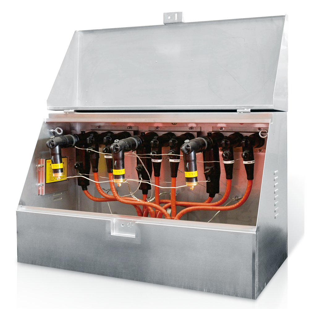
The American type cable distribution box produced by our company is widely applied to cabling engineering equipment in cable distribution network systems due to its excellent performance, standardized design and elegant appearance. It can be generally divided into 600A main circuit and 200A branch circuit types, and is widely used in various places such as major industrial parks, residential districts, urban complexes, fully enclosed and fully sealed high-rise buildings and high-rise fixed-point buildings. It features one-way opening and horizontal through-row arrangement as major characteristics, with flexible combination and compact structure. The 600A main circuit adopts plug-in screw fixed connection; the 200A branch circuit adopts plug-in connection and can be plugged and unplugged with load.
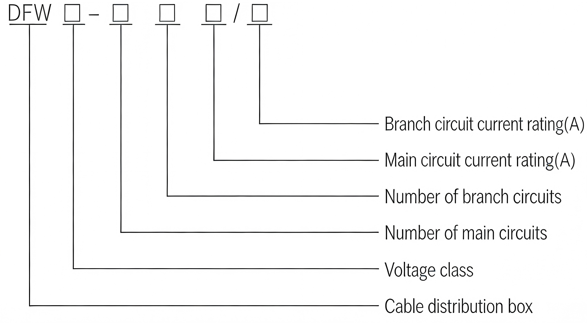
2. Model Meaning & Explanation
The coding of the product model contains the core structural characteristics and parameter information of the cable distribution box. The specific meaning of each part of the model is as follows:
DFW - □ - □ - □
3. Normal Operating Environment
- Ambient temperature: Maximum temperature +40℃, minimum temperature -30℃;
- Wind speed: Equivalent to 34m/s (not greater than 700Pa);
- Humidity: Daily relative humidity (not greater than 95%), monthly average relative humidity (not greater than 95%);
- Protection against impact: Horizontal acceleration not greater than 0.4m/s², vertical acceleration not greater than 0.5m/s²;
- Installation site inclination: Not greater than 30°;
- Installation environment: The surrounding air shall be free from corrosiveness, flammable gas, water vapor and obvious pollution, and the installation site shall be free from violent vibration.
- Note: If the ordered product exceeds the above specified conditions, please negotiate with our company.
4. Product Characteristics
- Excellent performance and standardized structural design, with elegant appearance and wide application range in cable distribution network systems;
- Flexible combination and compact structure, suitable for various application scenarios such as industrial parks, residential districts and urban complexes;
- 600A main circuit adopts plug-in screw fixed connection, and 200A branch circuit adopts plug-in connection which supports load plugging and unplugging;
- One-way opening and horizontal through-row arrangement design, convenient for installation and maintenance.
5. Core Technical Parameters
| Item | 200A (Branch Circuit) | 600A (Main Circuit) |
|---|---|---|
| Rated Voltage | 15kV | 15/25kV |
| Rated Current | 200A | 600A |
| Rated Short-time Withstand Current | 16kA/s | 60kA/s |
| 1-minute Power Frequency Withstand Voltage | 42kV | 42kV |
| 15-minute DC Withstand Voltage | 53kV | 78kV |
| Lightning Impulse Withstand Voltage | 95kV | 95kV |
| Minimum Corona Inception Voltage | 11kV | 19kV |
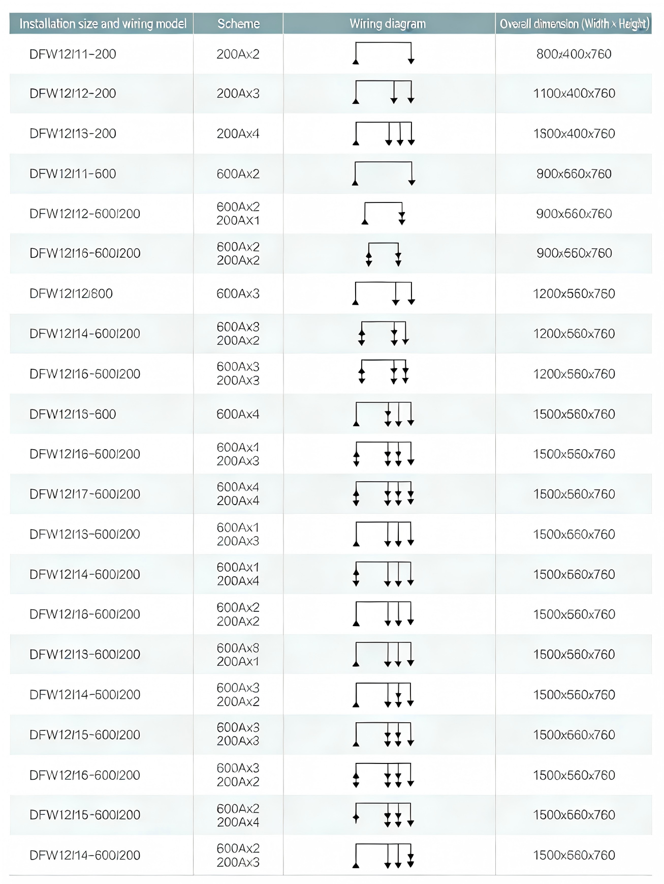
6. Model Specifications & External Dimensions
| Model of American Type Branch Box | Scheme | Wiring Scheme | External Dimensions (Length×Width×Height, mm) |
|---|---|---|---|
| DFW12/1-200 | 200A×2 | ┌─┐ ┌─┐ | 800×400×760 |
| DFW12/2-200 | 200A×3 | ┌─┐ ┌─┐ ┌─┐ | 1100×400×760 |
| DFW12/3-200 | 200A×4 | ┌─┐ ┌─┐ ┌─┐ ┌─┐ | 1300×400×760 |
| DFW12/1-600 | 600A×2 | ┌─┐ ┌─┐ | 900×560×760 |
| DFW12/3-600/200 | 600A×2 200A×1 | ┌─┐ ┌─┐ ┌─┐ | 900×560×760 |
| DFW12/2-600 | 600A×3 | ┌─┐ ┌─┐ ┌─┐ | 1200×560×760 |
| DFW12/4-600/200 | 600A×3 200A×3 | ┌─┐ ┌─┐ ┌─┐ ┌─┐ ┌─┐ ┌─┐ | 1200×560×760 |
| DFW12/5-600/200 | 600A×3 200A×3 | ┌─┐ ┌─┐ ┌─┐ ┌─┐ ┌─┐ ┌─┐ | 1200×560×760 |
| DFW12/3-600 | 600A×4 | ┌─┐ ┌─┐ ┌─┐ ┌─┐ | 1500×560×760 |
| DFW12/6-600/200 | 600A×4 200A×3 | ┌─┐ ┌─┐ ┌─┐ ┌─┐ ┌─┐ ┌─┐ ┌─┐ | 1500×560×760 |
| DFW12/7-600/200 | 600A×4 200A×4 | ┌─┐ ┌─┐ ┌─┐ ┌─┐ ┌─┐ ┌─┐ ┌─┐ ┌─┐ | 1500×560×760 |
| DFW12/3-600/200 | 600A×1 200A×3 | ┌─┐ ┌─┐ ┌─┐ ┌─┐ | 1500×560×760 |
| DFW12/4-600/200 | 600A×4 | ┌─┐ ┌─┐ ┌─┐ ┌─┐ | 1500×560×760 |
| DFW12/13-600/200 | 600A×2 200A×2 | ┌─┐ ┌─┐ ┌─┐ ┌─┐ | 1500×560×760 |
| DFW12/13-600/200 | 600A×2 200A×1 | ┌─┐ ┌─┐ ┌─┐ | 1500×560×760 |
| DFW12/14-600/200 | 600A×3 200A×2 | ┌─┐ ┌─┐ ┌─┐ ┌─┐ ┌─┐ | 1500×560×760 |
| DFW12/15-600/200 | 600A×3 200A×3 | ┌─┐ ┌─┐ ┌─┐ ┌─┐ ┌─┐ ┌─┐ | 1500×560×760 |
| DFW12/16-600/200 | 600A×4 200A×3 | ┌─┐ ┌─┐ ┌─┐ ┌─┐ ┌─┐ ┌─┐ ┌─┐ | 1500×560×760 |
| DFW12/15-600/200 | 600A×3 200A×4 | ┌─┐ ┌─┐ ┌─┐ ┌─┐ ┌─┐ ┌─┐ ┌─┐ | 1500×560×760 |
| DFW12/14-600/200 | 600A×2 200A×3 | ┌─┐ ┌─┐ ┌─┐ ┌─┐ ┌─┐ | 1500×560×760 |
7. Structural Description
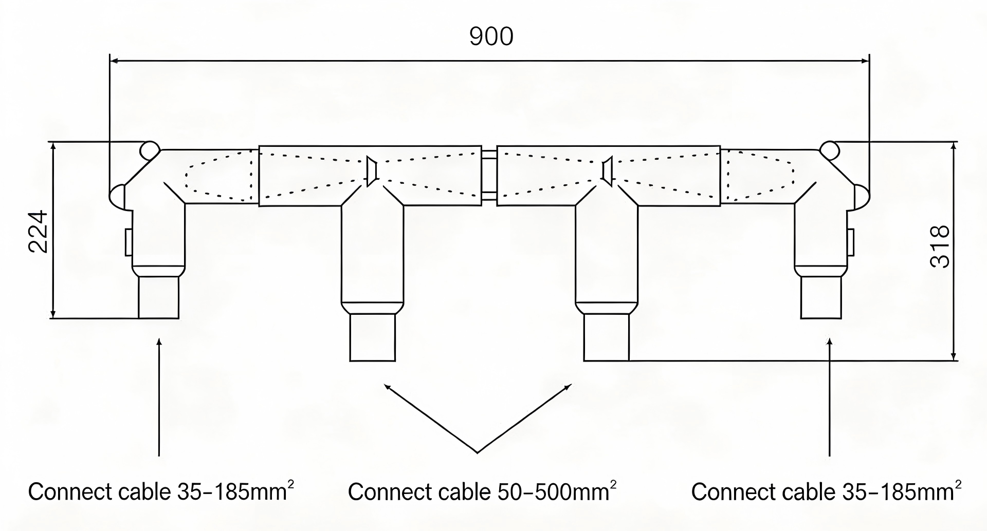
If the cable distribution box cannot be placed due to site limitations, it can be directly combined by cable connectors to form multi-circuit cable branching (no need for busbars, see examples for connection methods) and placed in a cable trench or other locations. Example 1: Four-way incoming and outgoing lines (2×600A+2×200A)
Each group consists of two T-II type cable connectors, two sealing connectors and one intermediate connection head. T-II type cable connector (200A) is connected with a sealed cable connector (the other side is connected with a full-insulation metal oxide arrester). See the following figure for dimensions:
Example 2: Three-way incoming and outgoing lines (3×600A)
Each group consists of three T-type cable connectors and two intermediate connection heads. See the following figure for dimensions and examples:
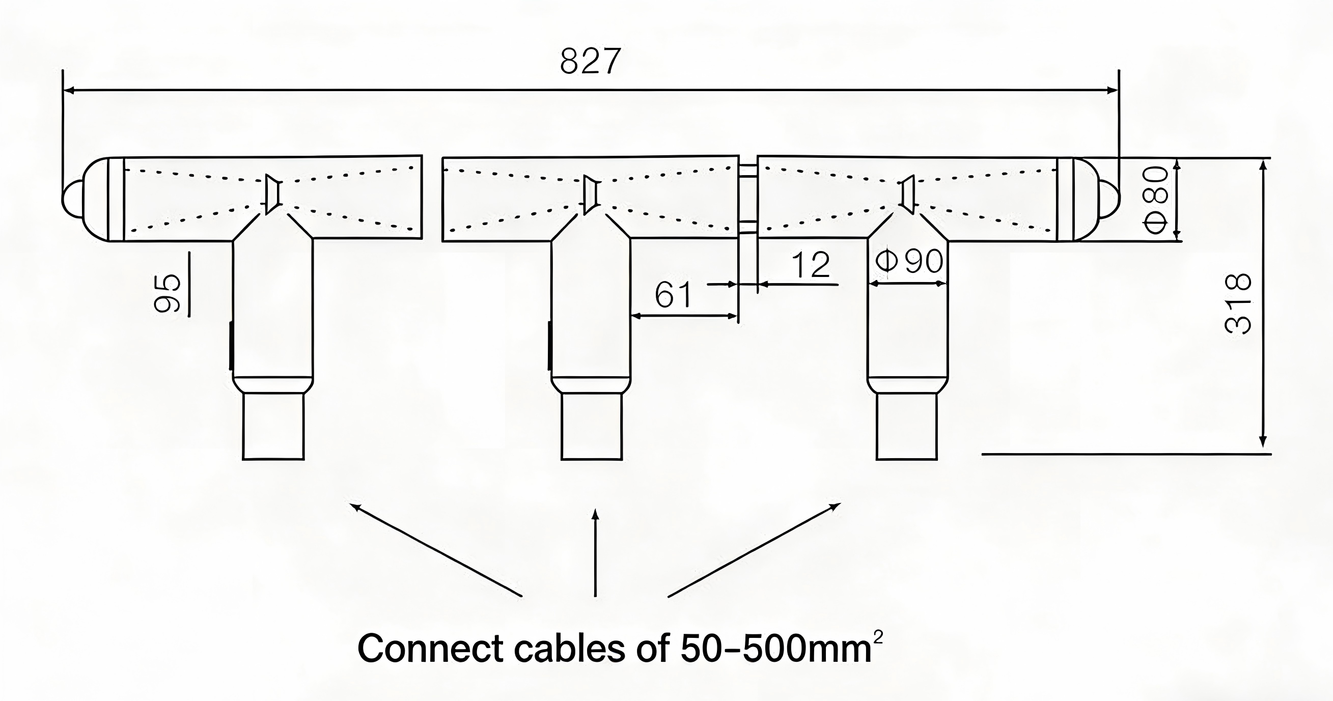
Note: Cable branching can be arbitrarily expanded or reduced according to needs, and can be placed outside the box body or directly buried in the cable trench.
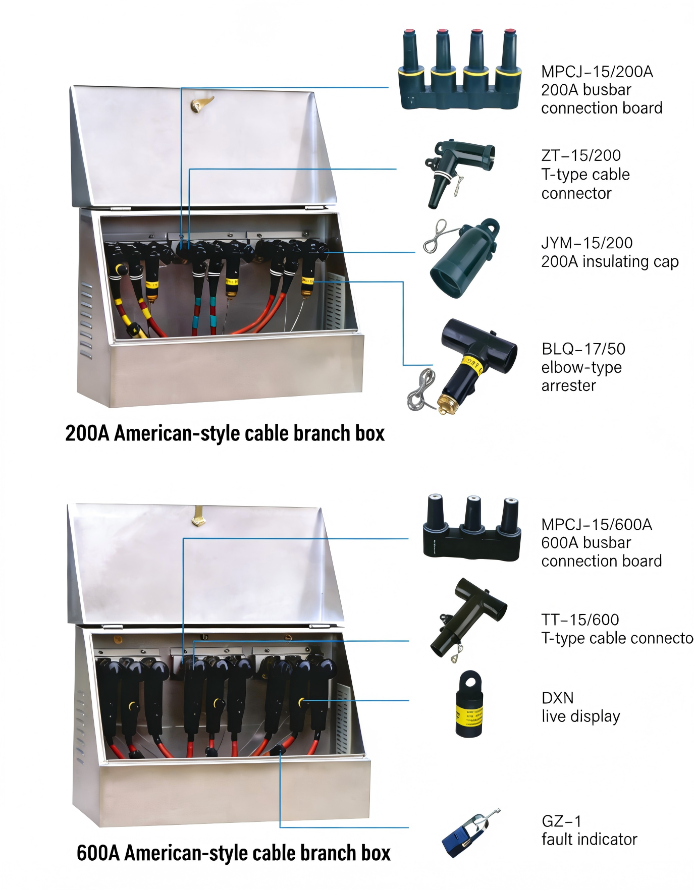
8. Accessory Description
200A American Type Cable Distribution Box Accessories:
- MP□-15/200A: 200A busbar board
- ZT-15/200: Sealed cable connector
- JY-M-15/200: 200A insulation cap
- BLQ-17/50: Sealed arrester
600A American Type Cable Distribution Box Accessories:
- MP□-15/200A: 600A busbar board
- TT-15/600: T-type cable connector
- DXN: Live display
-
GZ-1: Fault indicator
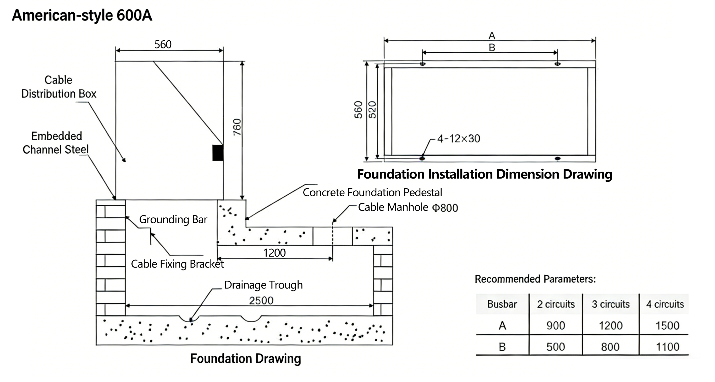
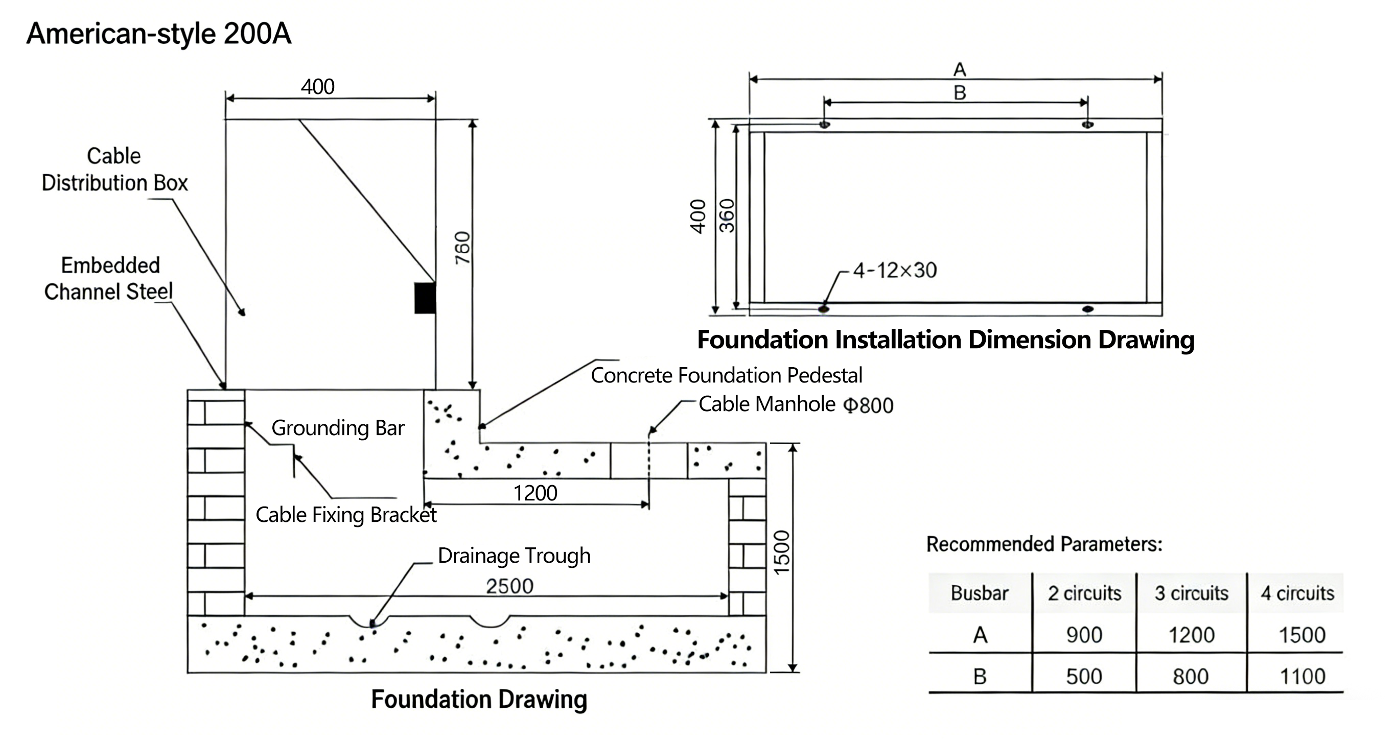
9. Foundation Drawing
9. Ordering Notes
When placing an order for the American type cable distribution box, please provide the following information to ensure that the product meets the actual use requirements:
- Exact product model and specification (including main circuit/branch circuit current rating);
- Required external dimensions and wiring scheme;
- Operating environmental conditions (if special requirements such as high altitude, high humidity);
- Special technical requirements (such as customized accessories, special connection methods);
- Requirements for accessories and supporting components.

")
 Fixed Enclosed Switchgear")


